61
UMG 509
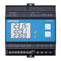
Connection schematic, current measurement
The following connection schematics can be selected
for the current measurement:
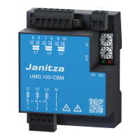
3p4w - 3 phases, 4 conductors, 3 current
transformers
3p5w - 3 phases, 4 conductors, 4 current
transformers
The fourth current transformer can be used
for the measurement in the
neutral conductor for example.
3p2i - 3 phases, 4 conductors, 2 current
transformers
For networks with symmetrical loading.
3p2i0 - 3 phases, 3 conductors, 2 current
transformers
Aron circuit for networks without
neutral conductor. The third current will
be calculated
1p2i - 1 phase, 2 conductors, 2 current
transformers
Factory default setting: 3p4w
C
It is not necessary to configure a
connection schematic for measurement
inputs V4 and I4.

 Loading...