External Control (I/O / Fieldbus) 22 DESKTOP ROBOT JR3000
2.5
Wiring Layout Check (PNP)
Once the external device is connected to I/O-SYS or I/O-1, make sure you perform the following
checks before turning ON the electricity. This page describes the robot’s I/O polarity for PNP
specifications. For NPN specifications refer to “2.4 Wiring Layout Check (NPN).” The robot’s
I/O polarity can be confirmed by checking the I/O nameplate. Refer to “3.1 I/O Polarity” in the
operation manual
Specifi cations
for details about the I/O polarity.
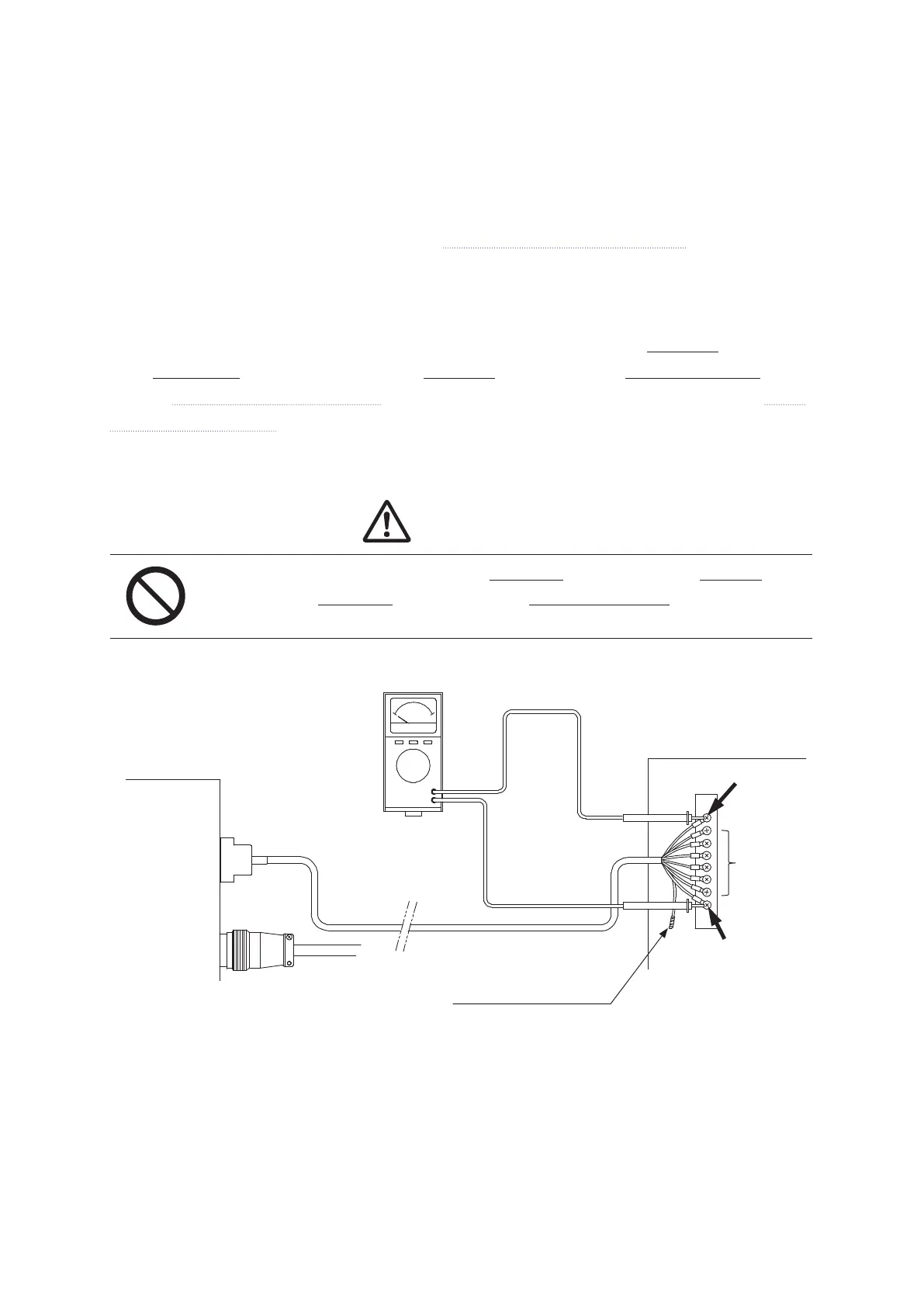
Refer to the diagram below and check each pin to make sure that none of the GND pins are shorted
to the DC 24 V pin, and also that none of the GND pins are shorted to the output signal pins.
Refer to “2.12 Circuit Diagram (PNP)” for details regarding I/O-SYS connections or refer to “8.11
Circuit Diagram (PNP)” for details regarding I/O-1 connections.
Caution
Do not turn ON the power if any of the GND pins are shorted to the DC 24 V pin,
or if any of the GND pins are shorted to the output signal pins.
The robot’s internal circuits may be damaged when the power is turned ON.
*
If there is an unconnected wire amongst the wire connections, make sure you wrap electrical
insulating tape over the copper wire parts and on the end of the wire to prevent the wire from
touching other wires etc.; thereby shorting them out.
I/O-SYS
I/O-1
JR3000
GND Pin
DC 24 V Pin
Tester
Deal with loose wires*
Output
signal
pins
External Device Example
 Loading...