Do you have a question about the Jaquet FT 3000 and is the answer not in the manual?
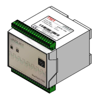
Describes the front panel of the FTFU 3024 module, including LEDs and functions.
Describes the front panel of the FTV 3090 relay card module.
Describes the front panel of the FTK 3072 communications module.
Describes the front panel of the FTW 3013 frequency to current converter module.
Describes the front panel of the FTBU 3034 module, including signal monitoring channels.
Provides statistical data such as Mean Time Between Failure (MTBF) for system components.
Details specifications related to IEC 61508-2-3 standard compliance for safety integrity.
Lists technical data for the Overspeed Protection System (OSPS), including measuring ranges.
Explains the overall measuring system architecture and signal flow.
Details the fundamental principles of measurement, including value standardization, speed monitoring, and frequency measurement.
Describes how measured values are standardized using machine factors or pulses per revolution.
Explains the functionality and operation of the speed monitor circuits.
Covers frequency measurement, measurement functions, max value memory, comparators, and analog outputs.
Explains how acceleration is measured and its associated accuracy definitions.
Describes the power supply monitoring for modules, including LED status and internal messages.
Explains the monitoring of internal voltages within modules and the NMI alert.
Details static and dynamic sensor monitoring methods and fault detection.
Covers system self-tests and fault detection for modules, including OK-LED status.
Explains the module OK status and how it influences relay control.
Describes fault conditions and their impact on system behavior and limit value control.
Provides general installation guidelines, safety precautions, and earth connection requirements.
Details specific installation rules related to IEC 61508-2-3 compliance for system installation.
Outlines the software concept for parameter configuration, including parameter lists.
Explains communication setup between PC and modules, including system requirements and software installation.
Covers parameter settings including system settings, sensor monitor, analog outputs, and limit values.
Describes system behavior during power up, measurement, sensor failure, alarms, and mains failure.
Covers frequency measurement calibration, tools, accuracy factors, and calibration rules.
Details the process and rules for calibrating the sensor monitor function, including accuracy factors.
Describes the FTFU 3024 motherboard circuitry, including frequency measurement and supply.
Details the frequency measurement implementation using ASIC's and input signals.
Explains the speed monitor implementation in ASIC's and their measuring capabilities.
Describes the internal micro controller, RAM, A/D converter, and EPROM.
Details the supply voltage generation and monitoring on the FTFU 3024 from redundant PSUs.
Explains the NMI reset circuit and its functions for monitoring voltage and triggering reset routines.
Describes the input amplifier circuit for signal input, including protection and filtering.
Details static and dynamic sensor monitoring methods, including LED indicators and relay assignments.
Explains the functions for module status monitoring, including System OK, PS OK, and Sensor OK.
Describes the relay outputs on the motherboard and their possible assignments.
Explains the configuration of limit LEDs for indicating upper and lower set points.
Describes the built-in frequency generator for test purposes and its selectable frequencies.
Details the available frequency outputs from the FTFU 3024 and their input signal programming.
Describes the binary inputs and their configurations, including common reference and floating reference types.
Explains the test function for the frequency generator, including OK-LED status.
Explains how direction of rotation is determined using phase relationships and signalled by LEDs.
Describes the lamp test activation for all FTFU 3024 and auxiliary module LEDs.
Details the supply of the FTW 3013 module via the local bus.
Describes the analog output capabilities of the FTW 3013, including digital control and filtering.
Details the supply of the FTV 3090 relay card via the local bus.
Describes the relay outputs on the FTV 3090 card and their possible assignments.
Explains the rack bus communication interface used by the FTK 3072.
Details the RS 232 interface specifications, connection diagram, and voltage protection.
Explains the periodic test procedure for system verification and IEC 61508-2-3 compliance.
Covers troubleshooting procedures for OSPS, TCCC, and IEC 61508-2-3 specifications, including specific steps for each.
Provides general guidelines for module exchanging and details IEC 61508-2-3 specifications for module replacement.
| Brand | Jaquet |
|---|---|
| Model | FT 3000 |
| Category | Measuring Instruments |
| Language | English |