77
Use the following steps to mechanically operate the room:
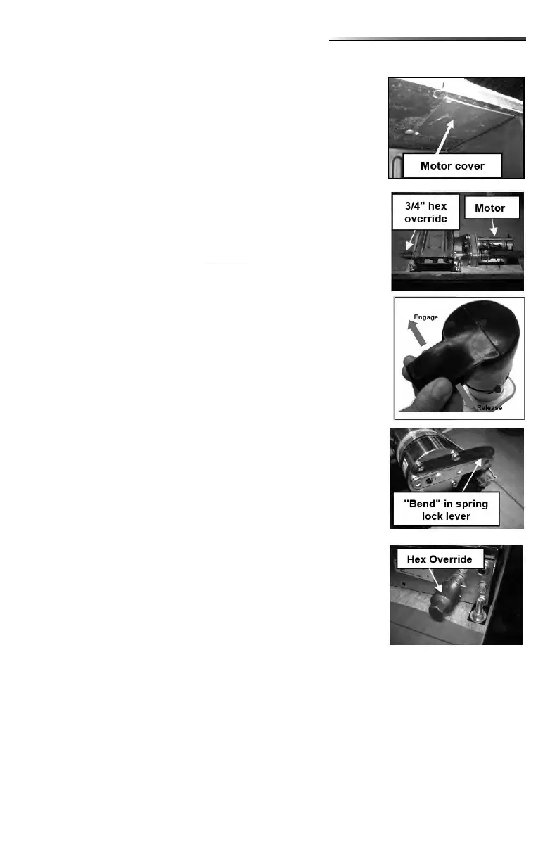
1. Locate the ABS motor access cover for the slideout. This
cover will be located inside one of the storage compart-
ments under the slide room up at the top of the compart-
ment.
2. Remove 4 screws holding the panel to the top of the com-
partment. Remove the cover.
3. Unplug the motor leads at the connector. Gray connector
with red and black wires.
4. To release the motor brake you must depress the spring
lock lever, which then allows you to pivot the brake lever,
which in turn releases the brake. These parts are located
inside the rubber boot wire tied over the motor. You must
manipulate these parts removing the rubber boot.
These photos will help
you gure out how this works. The side-by-side photo (be-
low) shows the spring lock lever and the brake lever.
5. The spring lock lever is a thin metal arm with a slight bend
at the end, which will hold the brake lever in the released
position.
6. The brake lever is the heavier thicker metal arm with the
hole in the end.
7. The normal position for these two levers is to be parallel
to each other as shown in the rst side-by-side photo. The
motor brake is engaged with levers side by side.
8. The brake lever is moveable; the spring lock lever is not
moveable. To release the brake lever, you must push the
bent end of the spring lock lever away from the brake le-
ver; this will allow you to pivot the brake lever so it moves
over on top of the spring lock lever. The bent end will
hold the brake lever in the released position. (photo shows
this “bend”).
9. Once the brake motor is released, you will need to remove
the skirting on the side of the slideout oor where the hex
override is located.
10. Use a ratchet with a 3/4” socket (or wrench) to turn the
hex override and manually move the slideout.
11. When the slideout is retracted, check to make sure you
have a good seal, and replace the skirting on the slideout.




 To Next Page