ENGLISH
6
SOLDERING PROCEDURE
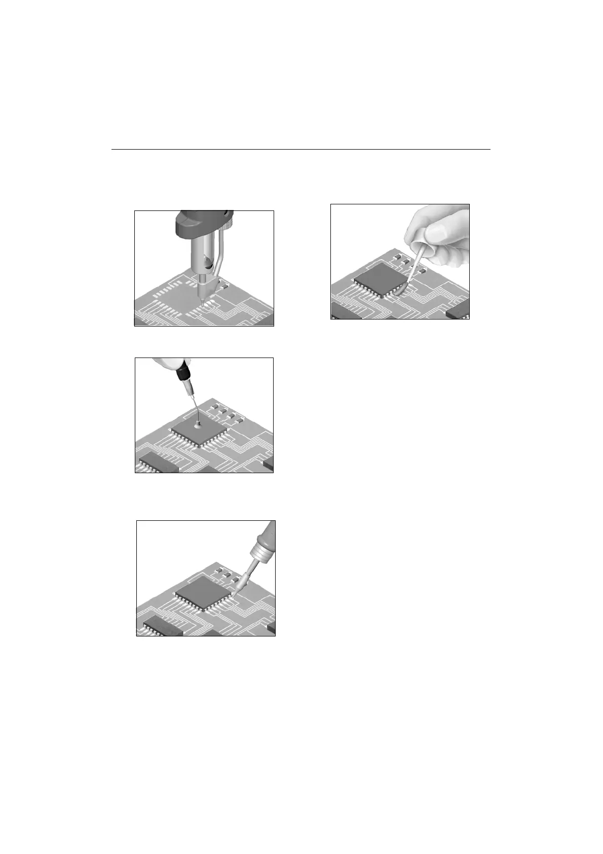
1 After desoldering the component, any solder
left on the printed circuit should be removed
with our DR 5650 desoldering iron ref. 5650000.
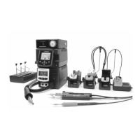
4 Apply FL 9582 flux ref. 0046565 in pads and
leads.
5 Solder the remaining pins. For this we
recommend to use our soldering irons of the
JBC series, which are available in two different
models:
2210 handpiece ref. 2210000 for great
precision tasks, like SMD solders, etc.
2245 handpiece ref. 2245000 for general
soldering tasks in professional electronics.
These soldering irons have a wide range of
cartridges with different models of tips. The
2245-009 cartridge and 2245-010 are
specially designed for soldering SMD circuits
of the QFP and PLCC types.
Solder wire with a diameter of between 0.5 and
0.7 mm should be used.
2 Place the component or printed circuit with
the MP 2260 Pick & Place ref. 2260000.
3 When the component is correctly placed,
solder its pins.In the case of integrated circuits
of the Flat Pack type, first solder one pin of
every IC angle to fix it in place in the circuits.
6 Depending on the nature of the component to
be soldered, use soldering paste together
with our TE 5400 hot air station, which gives
very accurate air-flow regulation, between 4
and 12 l/min.