Service
Notes
Performance
Checks
All
performance
checks
are
in-cabinet procedures
to be
used
for
checking
specifications
after
repair or for
incoming
quality
control
inspection.
Note:
All
measurements should
be made
with
the
5306
and
test
equipment power
cords connected
to
a nominal
120
V
AC,
50/60
Hz line
voltage.
The
following
test
equipment
is recommended:
Audio
Test
Oscillator—
Krohn-Hite model
4100,
or
equivalent.
Harmonic
Distortion
Analyzer—
Hewlett Packard
Model
333A,
331 A
or
equivalent.
Intermodulation
Distortion
Analyzer—Crown
Model IMA,
or
equivalent.
AC
Voltmeter—
Hewlett Packard
Model
427A
or
equivalent.
5.
Voltage
gain
of
the system
can be checked
by
substituting
PO
the values
in
the
formula
A (dB)
=20Log
V
10
ein
6.
Input
voltage
to
the
system
can be measured
by connect-
ing
the AC voltmeter
at the
input terminal.
Total Harmonic Distortion
1
.
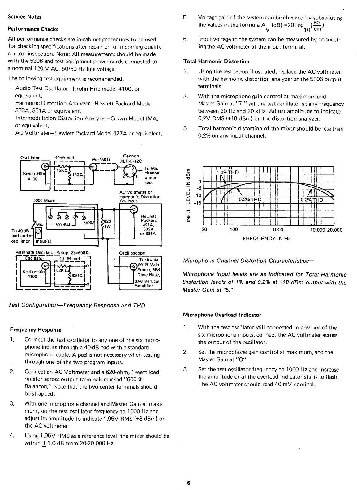
Using the test set-up
illustrated,
replace the
AC voltmeter
with the
harmonic
distortion analyzer
at the 5306
output
terminals.
2.
With the microphone
gain control
at maximum
and
Master
Gain
at
"7,"
set the test oscillator
at any frequency
between
30
Hz
and 20 kHz. Adjust
amplitude
to
indicate
6.2V RMS (-MS
dBm) on the distortion
analyzer.
3.
Total harmonic
distortion
of
the mixer
should
be less
than
0.2% on any input
channel.
Oscillator
I
I
5306
Mixer
*MiC
To
40
dB
pad and^
oscillator
eoOnBAL—
1
pND
Input(s)
Alternate
Oscillator
Setup:
Zs=600.fl.
r~
Oscillator
^
^B_pad~*
"T
I
Ur
—
f-
vWH
Krohn-Hitej
l62KnJ
4100
’
'
,620ni
J620
MW
AC
Voltmeter
or
Harmonic
Distortion
Analyzer
Hewlett
Packard
427A,
333A
or
331
A
Oscilloscope
Tektronix
_£^561B Main
'^Frame,
3B4
I
Time
Base,
I3A6
Vertical
Amplifier
20 100
1000
10,000 20,000
FREQUENCY IN Hz
Microphone Channel Distortion
Characteristics—
Microphone input
levels are
as indicated
for
Total
Harmonic
Distortion levels
of
1%
and 0.2%
at
+18
dBm
output with
the
Master Gain at
"5.”
Test Configuration
—
Frequency
Response
and
THD
Frequency
Response
1.
Connect
the
test
oscillator to any
one
of
the six
micro-
phone
inputs
through
a 40-dB pad
with
a
standard
microphone
cable.
A pad is
not necessary when testing
through
one of
the two program inputs.
2. Connect
an
AC
Voltmeter and a 620-ohm, 1-watt load
resistor
across
output terminals marked
"600 n
Balanced."
Note
that the two center terminals should
be
strapped.
3.
With
one
microphone
channel and
Master
Gain at maxi-
mum,
set the
test
oscillator frequency
to
1000
Hz
and
adjust
its
amplitude
to indicate
1.95V
RMS
(-f
8
dBm)
on
the
AC
voltmeter.
4. Using
1 .95V
RMS
as a
reference level, the mixer should
be
within
+
1.0 dB
from 20-20,000 Hz.
Microphone
Overload
Indicator
1
.
With
the test oscillator
still connected
to any one of
the
six
microphone
inputs, connect the
AC
voltmeter
across
the
output
of
the oscillator.
2.
Set the microphone
gain control at
maximum, and
the
Master
Gain
at
"0".
3.
Set the
test oscillator
frequency
to 1000 Hz
and increase
the amplitude
until the overload indicator
starts to flash.
The
AC
voltmeter
should
read
40 mV nominal.
6


 To Next Page
 Loading...