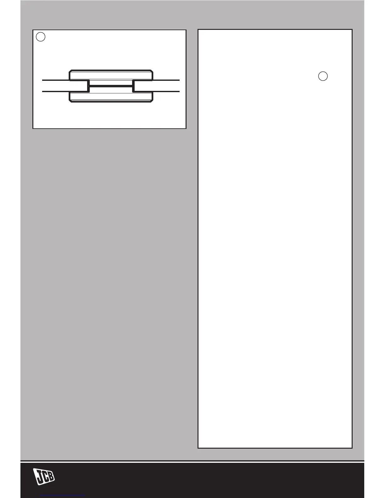
grinding discs the raised part of the
outer flange is fitted facing towards
the disc to provide improved
support for the disc hole (See
4
).
Always ensure your disc is securely
clamped.
ADJUSTING THE
PROTECTION GUARD
Before any work on the machine
itself, pull the mains plug.
For work with grinding or cutting
discs, the protection guard must
be mounted.
The coded projection (12) on the
protection guard (10/13) ensures
that only a guard that fits the
machine type can be mounted.
Loosen the clamping screw (11), if
necessary.
Place the protection guard (10/13)
with coded projection (12) into the
coded groove on the spindle collar
of the machine head and rotate
to the required position (working
position).
The closed side of the protection
guard (10/13) must always point
to the operator.
Tighten clamping screw (11).
4