About the Product
Operator Station
16 9831/4300-1 16
Operator Station
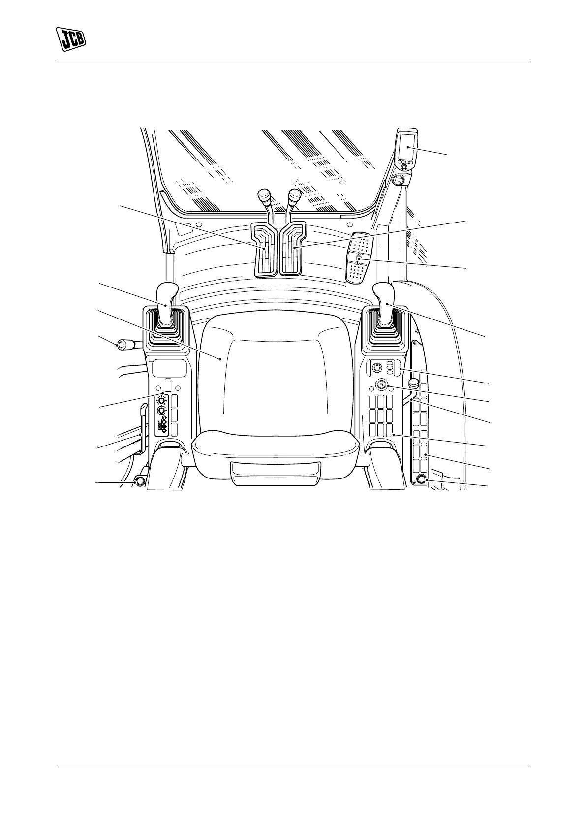
Component Locations
Figure 11.
A Left hand track control, Refer to: Track Controls
(Page 61).
B DECU (Display Electronic Control Unit), Refer
to: Instrument Panel (Page 65).
C Right hand track control, Refer to: Track
Controls (Page 61).
D Optional circuit pedal, Refer to: Auxiliary Circuit
Controls (Page 104).
E Right joystick, Refer to: Excavator Arm Controls
(Page 96).
F Machine power band controller, Refer to:
General (Page 64).
G Ignition switch, Refer to: Ignition Switch
(Page 17).
H Dozer lever,
J Right switch console, Refer to: Console
Switches (Page 19).
K 12V auxiliary power socket, Refer to: Auxiliary
Power Socket (Page 126).
L Door lever, Refer to: Operator Door
(Page 33).
M Left switch console, Refer to: Console Switches
(Page 19).
N Controls isolation lever,Refer to: Control Lock
(Page 59).
P Seat, Refer to: Operator Seat (Page 42).
Q Left joystick, Refer to: Excavator Arm Controls
(Page 96).
 Loading...