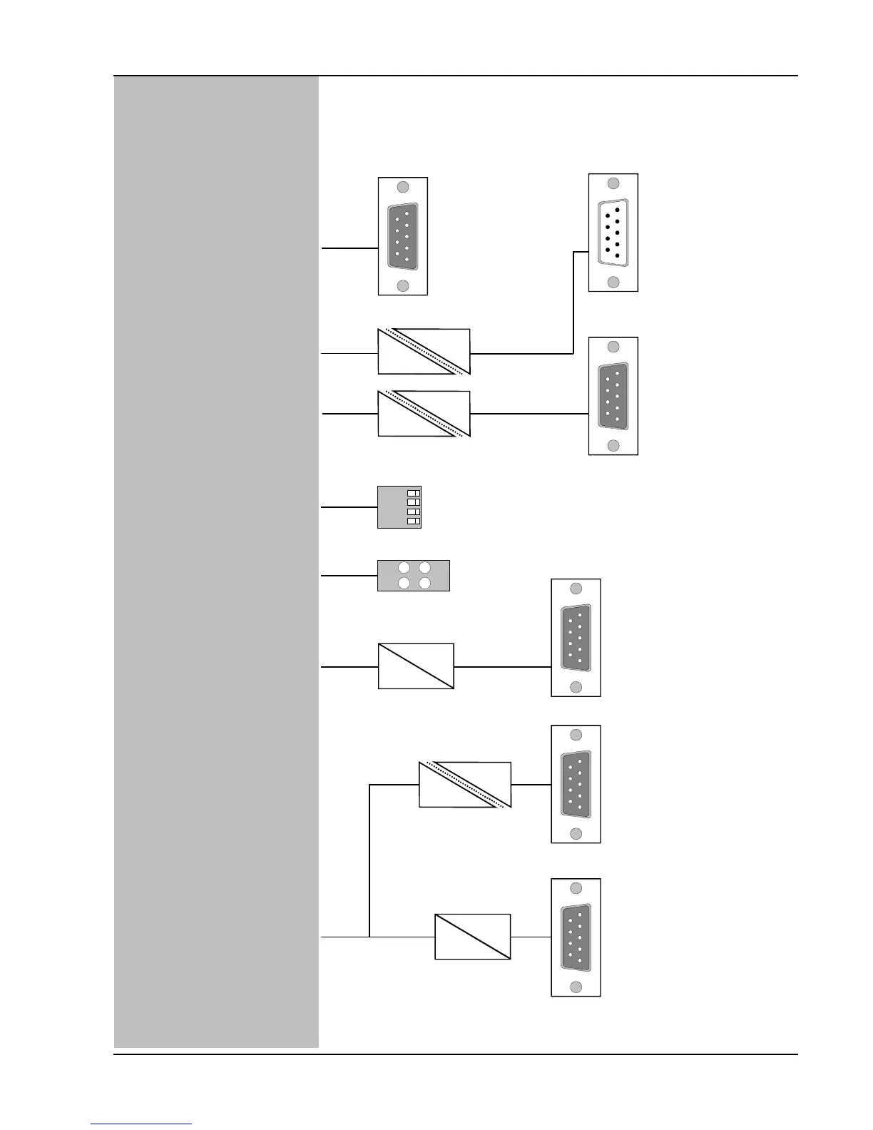
RS232 1:1 direct connection to a PC COM
RS232 serial interface for
parameter setting,
configuration, controlling
interface for setup by a PC
Fieldbus interface
CANopen, DS 402
Fieldbus interface, RS485 ,
published protocol
ID setting for
serial network operation
4 LEDs for indication of
device status
quadrature encoder input
for commutation, torque,
speed and positioning control
quadrature encoder input
configurable for pulse and direction
command for electronic gear
functions
Optional:
absolute value encoder input
(SSI)
max. 2 MHz
RS422
TTL
max. 2 MHz
RS422
TTL
Pin Signal at PC COM
1 DCD
2 RxD
3 TxD
4 DTR
5 GND
6 DSR
7 RTS
8 CTS
9 RI
D-Sub 9 pin
X 5
RS232
CAN
TTL
RS485
TTL
galvanic insulation
only with Profibus
S0
S1
S2
S3
24 V (gn)
BUS (gn)
RS422
TTL
D-Sub 9 pin male
X 1
CAN
Pin Signal
1 nc
2 CAN_L
3 CAN_GND
4 nc
5 nc
6 GND
7 CAN_H
8 nc
9 CAN_V+
FIELD BUS 1
D-Sub 9 pin
X 2
FIELD BUS 2
Code Switch
for Network-ID
0...15
Status-LED
ERR (rd)
D-Sub 9 pin
X 7
Master encoder input
Pin Signal
1 +5V, max. 200 mA
2 A (Clock)
3 B (Direction)
4 N
5 +24V
6 GND
7 / A (/Clock)
8 / B (/ Direction)
9 /N
MASTER ENCODER
D-Sub 9 pin
X 6
Motor encoder output
Pin Signal
1 +5V
2 A
3 B
4 N
5 nc
6 GND
7 / A
8 / B
9 /N
ENCODER OUT
D-Sub 9 pin
X 8
Motor encoder input
Pin Signal
1 +5V
2 A
3 B
4 N
5 nc
6 GND
7 / A
8 / B
9 /N
ENCODER IN
RUN (gn)
Jenaer Antriebstechnik GmbH ECOSTEP
200 S9 (13)
Safety Instructions / Technical Specifications / Installation, Date 09/2007
RS485 Profibus DP
Pin Signal Signal
1 frei frei
2 Rx + frei
3 Tx + RxD/TxD-P
4 frei CNTR-P
5 GND DGND
6 +5V VP (+5V)
7 Rx - frei
8 Tx - RxD/TxD-N
9 frei frei
 Loading...