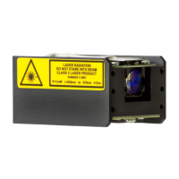
EasyManuals Logo

Jenoptik LDM51 Series User Manual

Jenoptik LDM51 Series
54 pages
To Next Page IconTo Next Page
To Previous Page IconTo Previous Page
Page #14 background imageLoading...
Page #14 background image
Device description
LDM52 OEM, Release 003, Revision 000
13
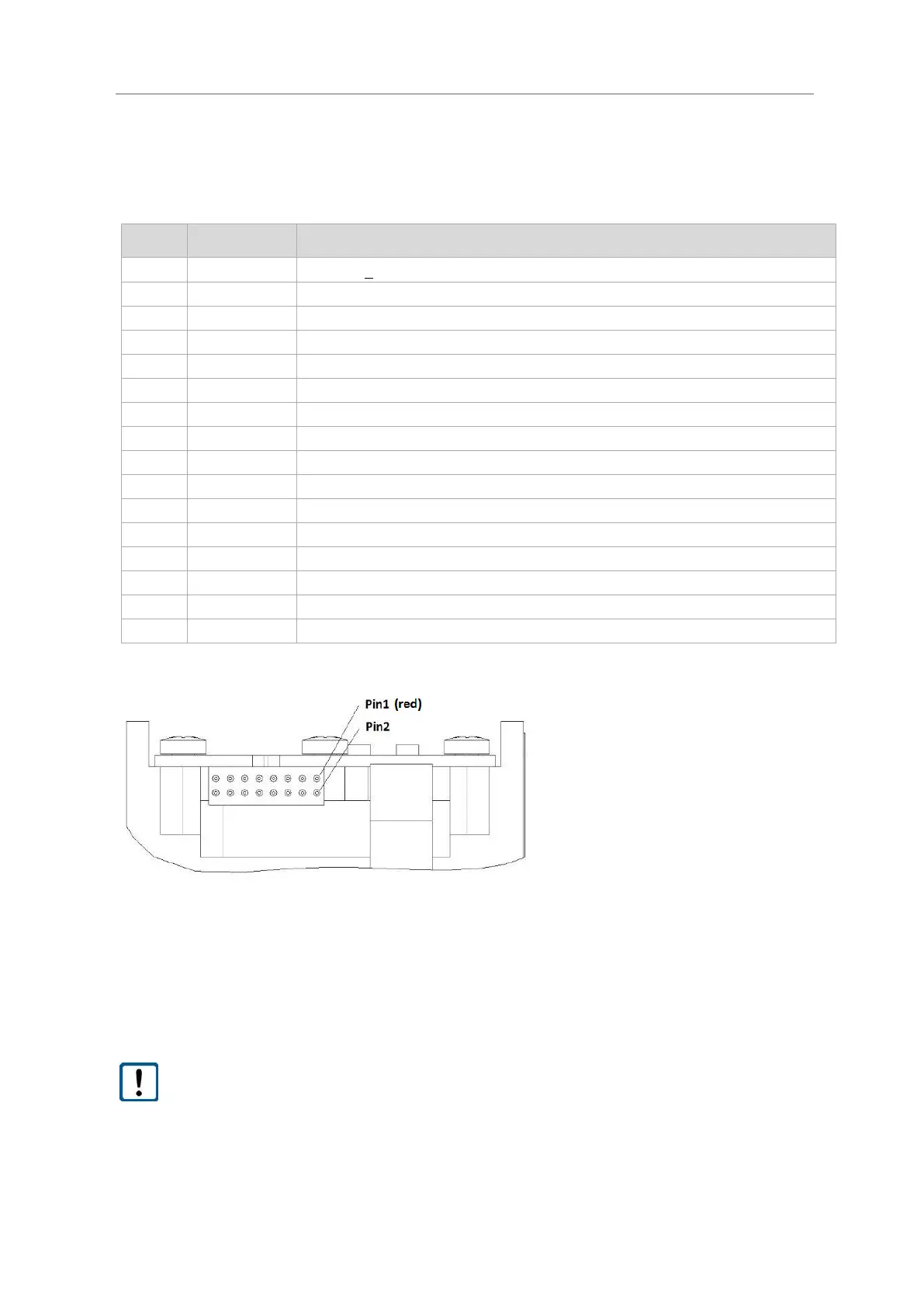
4.3 Device cable connector pin assignment
PIN
Signal
Description
1
5P
Power 5 + 0.5 V DC
2
TXD
RS232 TxD: level 3,3V CMOS
3
GND
Ground
4
RXD
RS232 RxD: level 3,3V CMOS
5
GND
Ground
6
Q1
Switching output Q1: level 3,3V CMOS
7
GND
Ground
8
Q2
Switching output Q2: level 3,3V CMOS
9
GND
Ground
10
Q3
Switching output Q3: level 3,3V CMOS
11
GND
Ground
12
TRIG
Triggerinput and output: level 3,3V CMOS
13
GND
Ground
14
QA
Analog output (3 … 21mA): load impedance ≤ 500Ω
15
NBOOT
Boot input (low active)
16
HEIZ_EN
Controller output for heater (high active) ;level 3,3V CMOS
Figure 2 Connector, pin configuration
Related connector, female inclusive flat cable: FFSD-08-D-06.00-01-N (Samtec)
 Inverse polarity protection is provided.
 Overvoltage protection is provided up to a maximum of 5.5 V DC.
Open, unused cable wires must be insulated.

Table of Contents

Questions and Answers:

Question and Answer IconNeed help?

Do you have a question about the Jenoptik LDM51 Series and is the answer not in the manual?

Jenoptik LDM51 Series Specifications

General IconGeneral
BrandJenoptik
ModelLDM51 Series
CategoryMeasuring Instruments
LanguageEnglish