Do you have a question about the Jensen WOODCHIPPER and is the answer not in the manual?
Explanation of safety pictograms, their meaning and placement.
Operator must read and follow the manual and safety instructions.
Do not open or remove safety shields while the engine is running.
Never reach into the rotating auger.
Essential safety rules and accident prevention guidelines for operation.
Adhere to general legal safety and accident prevention instructions.
Check all equipment is in good working order before starting work.
Wear tight clothing, safe shoes, eye, ear, and head protection.
Guidelines for adding and managing weights on the machine.
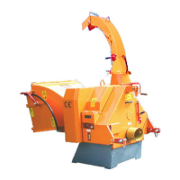
Operating instructions for wood chippers with internal combustion engines.
Exercise caution near fuel due to fire risk; avoid flames, sparks, hot metal.
Safe operating procedures and guidelines for using the wood chipper.
Do not place hands in the funnel - rotating pieces.
Never leave the wood chipper unattended when in use.
Crucial safety measures to be followed during machine operation.
Safety guards must always be in position and tightly secured during operation.
Ensure disc has completely stopped before opening the disc cover.
Regular checks and maintenance tasks for the wood chipper.
Ensure knife holder screws are tightened correctly; re-check after 1 hour.
Declaration of compliance with EU directives for the machine.
Procedures and safety precautions for motor maintenance.
Safety guidelines for electrical work and connections.
Safety guidelines and precautions for the hydraulic system.
High pressure fluids can penetrate skin and cause injury; seek medical attention.
Safety precautions for working with wheels and tyres.
General safety information and references for working with the wood chipper.
References for machine attendance, installation, and inspection work.
Check chipper after 50 hours, then every 100 hours or six months.
Procedure for starting the hydraulic system after changing hydraulic oil.
Procedures for hydraulic system maintenance and checks.
Guidelines for knife sharpness, placement, and compensation.
Specifications for woodchippers, including maximum wood diameter.
Table of tightening torques for bolts and nuts of class 8.8 and 10.9.
Guidelines for PTO shaft use, connection, and safety.
Only use authorized Cardan shafts for PTO connection.
Ensure correct fitting and security of the Cardan shaft.
Instructions for tractor-mounted wood chippers.
Ensure PTO shaft is correct length and plastic guard is in good condition.
Procedures for starting the machine and engaging feeding.
Start machine at 540 rpm, disengaged feeding, and slow pivot rotation.
General advice for assembling the clamping set.
Symbols and meanings for safety and advice.
Guidelines for the proper assembly, disassembly, and use of the clamping set.
Specifications for tolerances and surfaces for good rotating process.
Step-by-step instructions for assembling the clamping set.
Step-by-step instructions for disassembling the clamping set.
Information and procedures related to the PTO shaft joint.
Clean PTO shaft, activate locking, operate quick-disconnect lock.
Procedure for adjusting PTO shaft length, including cutting and de-burring.
Table of dB(A) ratings at measuring points for different machine types.
Specific greasing instructions for the A231/A240 model.
Table detailing greasing points, quantity, and frequency for an 8-hour shift.
Information and technical data for the automatic overload regulator.
Nominal voltage, inputs, output, display, logic, accuracy, housing, connection.
Instructions for connecting the overload regulator unit.
Information regarding original spare parts for the machine.
Schematic diagram of the hydraulic system with numbered components.
List of hydraulic system parts with part numbers and designations.
Diagram and parts list for the hydraulic pump drive assembly.
Exploded view diagram of the A231 reduction gear assembly.
List of components for the A231 reduction gear with part numbers.
Diagram and parts list for the V-belt tensioner roller.
Ensure 3mm clearance between tensioner roller and V-belts.
Diagram showing the assembly of the main shaft.
List of components for the main shaft assembly.
Diagram illustrating the components of the 2-blade chipper disc.
List of components for the 2-blade chipper disc.
Diagram and parts list for the roller drive transmission.
Diagram and parts list for the upper roller assembly.
Diagram and parts list for the lower roller assembly.
Diagram and parts list for the A231 fixed ejector.
| Brand | Jensen |
|---|---|
| Model | WOODCHIPPER |
| Category | Indoor Furnishing |
| Language | English |