Figure 6
Fig
ure 5
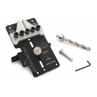
Figure 1
Setting the Drill Bit Depth Collar:
Usi
ng the
matching
stop collar for the drill bit you are using, screw
the ¼”-20 set screw into the stop collar. Now slide the
stop coll
ar
over the drill bit and with the
1/8” hex key
snug
the set
screw to
keep
the colla
r
in position. (See
Figure # 1)
** Note: Locate the set screw on the largest portion of the drill bit
not in one of the chip removal
flutes. (See
Figure # 1)
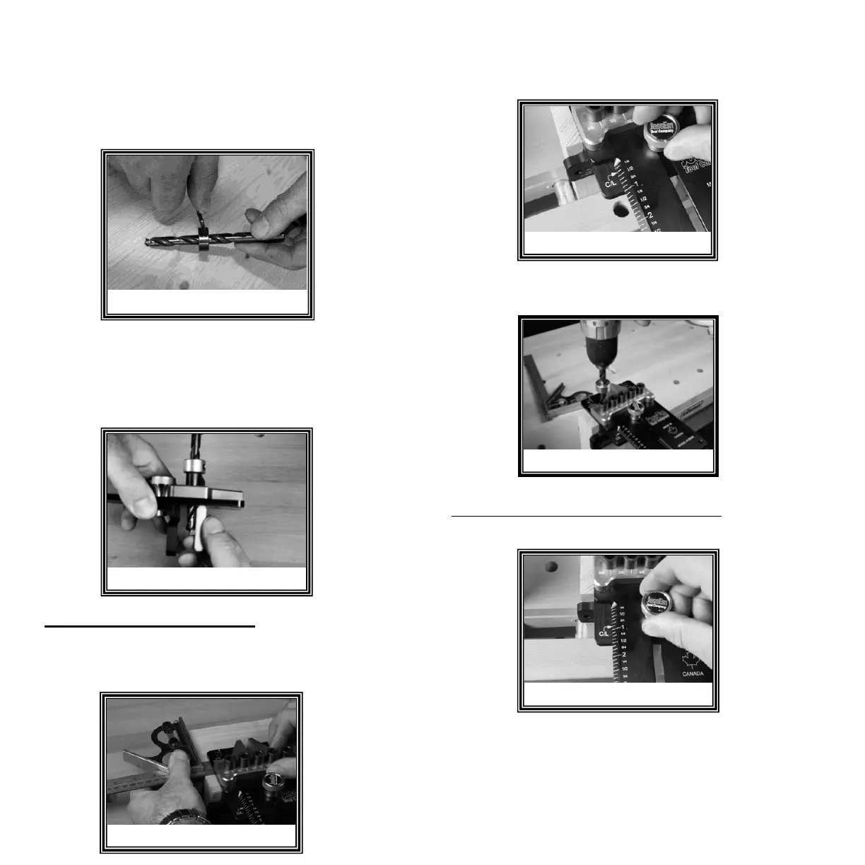
Figure 2
Figure 3
The first joint we are going to drill has 3 rows of dowels. We are
spacing our jig ½” from the edge. Clamp the jig to your board in
this position. (See Figure #3)
Figure 4
We want three (3) holes in this first row. One (1) in the center and
one (1) in
each
outside hole. (See Figure # 5)
With the first row drilled, adjust the jig to the 7/8” position.
Note: Do not unclamp the Jig from your board. (See Figure
#6)
MULTIPLE ROW DOWEL JOINT
Insert the drill bit into the corresponding drill bushing and measure
the amount the drill bit protrudes (See Figure # 2). The drill bit
should be deep enough to accomodate half the dowel you are
using. For thinner stock, ensure the dowel pin does not break
through your material and compensate by
drilling deeper on the
corresponding piece.
We have predetermined that we want the first row of dowels
spaced 3/8" of an inch in from the edge. Loosen the adjustment
knob and adjust the jig to the 3/8" position. (See Figure # 4)
5
 Loading...