FIG. 14
FIG. 18
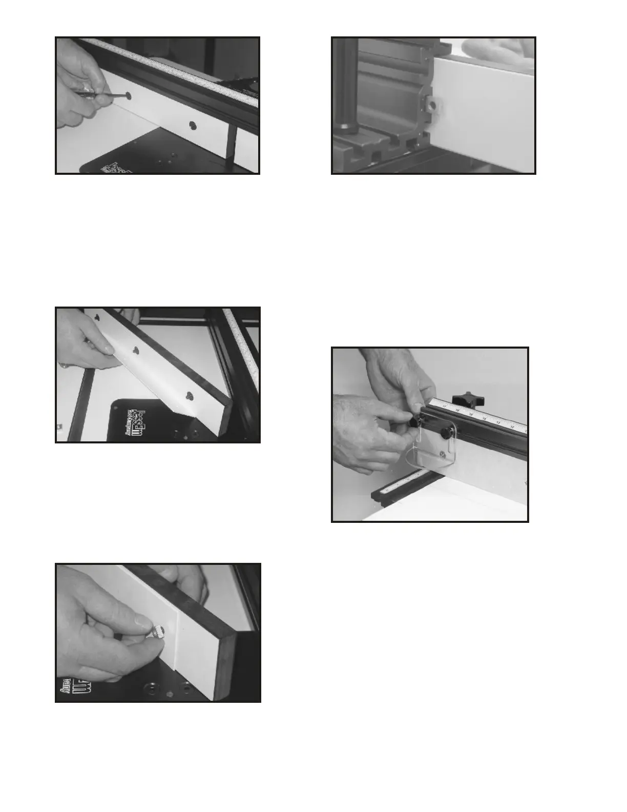
FIG. 15
FIG. 16
ATTACHING THE ROUTER BIT GUARD
21. Take the clear polycarbonate guard
(Part #16) and two of the black knurled
knobs (Part #2) and two 1/4” square nuts
(Part #7). Insert each knob through each
slot in the guard and thread a square nut
onto each bolt end.
22. Line up the nut on the guard assembly
and slide each nut into the T-slot starting
from the end of the fence (Fig. 18). Then
slide the guard to the center of the fence
and adjust the guard slightly higher than
and above the router bit. Be sure the guard
clears the bit. Adjust and tighten securely
before each use and after all bit changes.
INSTALLING THE JOINTING SHIM BEHIND
THE OUTFEED SUBFENCE.
17. Take the hex shape ball driver and
loosen the machine screws on the left side
subfence. Then slide the left subfence
completely off the left end of the fence.
18. Once removed from the fence frame
take off all three of the 1/4” square
retaining nuts and set aside. Take either the
1/32” or 1/16” thick shim and line up the
three holes in the shim with the three
machine screws protruding out the
backside of the subfence.
19. Thread the three 1/4” square nuts onto
the machine screws just until the bolt tip is
flush to the outside of the nut.
20. With the shim mounted to the back side
of the subfence and the square nuts
threaded onto the three machine screws,
line up each square nut and feed them one
at a time into the T-slot on the inside back
of the fence frame (Fig. 17). When all three
nuts are in the T-slot slide the subfence into
position and tighten the three machine
screws with the ball driver to complete the
installation of the shim.
FIG. 17
 Loading...