Do you have a question about the Jetter JX3-AO4 and is the answer not in the manual?
Explains general safety rules for users and compliance with regulations.
Details the qualifications required for personnel operating the device.
Outlines procedures for repair and maintenance, emphasizing authorized service.
Details precautions during module replacement.
Provides measures for increasing immunity against electromagnetic interference (EMI).
Details the JX3-AO4 module's characteristics and capabilities.
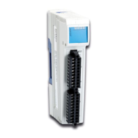
Identifies and describes the physical components and interfaces of the module.
Specifies the minimum software and hardware requirements for operation.
Details the signals connected to terminal X51 for analog outputs 1 and 2.
Details the signals connected to terminal X52 for analog outputs 3 and 4.
Explains how to connect voltage actuators to analog output 1.
Explains the function and meaning of the LEDs on the module.
Step-by-step guide for mounting the module onto a DIN rail.
Details the procedure for replacing a module on the backplane.
Step-by-step guide for detaching the module from the DIN rail.
Lists requirements for performing the first commissioning of the module.
Covers pre-commissioning checks and expected module behavior.
Details the commissioning process using a JC-3xx controller.
Details the commissioning process using a JC-24x controller.
Explains how registers and I/O numbers are assigned to JX3 modules.
Defines module registers and how they are used for data access.
Explains how I/O module numbers are assigned on the JX2 system bus.
Describes procedures for voltage and current output from analog outputs.
Introduces additional features available for analog outputs.
Explains how to define custom scaling for analog outputs.
Introduces four additional features for analog outputs.
Explains how to set error values and define fault condition behavior.
Introduces the internal oscilloscope function for recording module register values.
Explains how to monitor analog output status using collective bits in MR 0.
Explains the meaning of module LEDs for status and error indication.
Explains how to diagnose errors using module registers.
Describes errors related to invalid reference values.
Describes errors due to loss of communication with the controller.
Describes errors due to missing or corrupt operating system.
Describes errors related to the Digital-to-Analog converter.
Describes errors when internal auxiliary voltages are out of tolerance.
Explains how to read and interpret software version numbers.
Explains how to read EDS data from JC-3xx controller registers.
Explains how to read EDS data from JC-24x controller registers.
Explains how to identify module using registers like MR 9 and MR 32.
Explains how to identify the module using its nameplate.
Provides a high-level overview of register categories.
Summarizes register number composition for different controllers.
Summarizes bits in MR 0 (Module State).
Lists commands available via MR 1y01.
Lists registers for user-defined scaling configuration.
Details terminal assignments for analog outputs 1 and 2.
Details terminal assignments for analog outputs 3 and 4.
Section containing electrical, mechanical, and operating data.
Presents diagrams and dimensions of the module.
Lists operating parameters for environment: temperature, humidity, pollution.
Lists mechanical parameters like vibration, shock, and protection degree.
| Category | Control Unit |
|---|---|
| Number of Outputs | 4 |
| Output Type | Analog |
| Voltage Output Range | 0-10 V |
| Current Output Range | 0-20 mA |
| Resolution | 16-bit |
| Power Supply | 24 V DC |
| Output Range | 0-10 V / 0-20 mA |