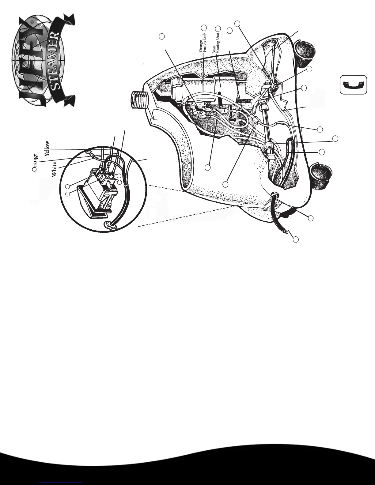
White
White from Cordset
2
6
5
13
Ground
Location
Element
Mounting
Screws
Blue Wire
12
L-290
Thermostat
Black from Cordset
Green
Black
from
Cordset
6
5
4
8
3
7
7
2
1
1
1
Grounding
Strap
Green
Ground
W
ire
10
Yellow Wire
White Wire
9
3
Brass
Nut
Brass
Nut
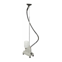
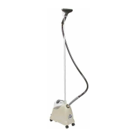
Worldwide Leader
in Steaming Equipment
Since 1940
Jiffy
®
J-2000 Wiring Diagram
Jiffy Steamer Company, LLC
4462 Ken-Tenn Highway (38261) Post Office Box 869 Union City, Tennessee 38281-0869 United States of America
Phone: 1-731-885-6690 Fax: 1-731-885-6692 Web: www.jiffysteamer.com E-mail: jsinfo@jiffysteamer.com
Comments? Questions?
Jiffy Steamer Company
Hotline 1-800-J2-Jiffy
(1-800-525-4339)
1. Insert cord set (1) into housing and connect black positive wire (2) from
cord set to terminal number 5 on the switch.
2. Connect blue wire (4) from the right side of brass heating element (5) to
right side of the L-290 thermostat (6).
3. Insert brass heating element unit into housing. Hand tighten the brass nuts
(7) on the water line to the element and to the 90 degree fitting from the
cup. Tighten 2 mounting screws (8) at the base of heating element. Now,
use a 5/8” wrench to securely tighten the brass nuts on the water line to the
element and to the 90 degree fitting from the cup. Heating unit may be
loosened and adjusted for a better fit if necessary.
4. Place the copper 4 inch grounding strap as shown in drawing. Secure
grounding strap and the green ground wire with the grounding screw by
attaching to the heating element ground location (3).
5. Connect white wire (9) from the left side of the heater unit to terminal
n
umber 6 on switch.
6. Connect yellow wire (10) from the left side of the thermostat to terminal
number 3 on the switch.
7.
Connect white neutral wire (11) from cord set bundle to orange fusible link
with plastic connector (12).
8. Connect other end of orange fusible link to terminal number 2 on the
switch.
9. Set steamer upright and place black plastic strain relief (13) approximately
4 1/2” from end of cord set and insert into housing using pliers.
10. Secure bottom plate with four screws.
11. To avoid leakage, be sure to tighten hose (or hat nozzle) with wrench
before using steamer.
Before attempting any repair on a Jiffy Steamer product, make sure that it
is unplugged from the outlet. If you have any questions, please contact our
repair department at 1-800-525-4339 between 7:30 AM - 4:00 PM Central
Standard Time.
Please note switch terminal 2, 3, 5 and 6 indicated on the enlarged switch
dia
g
r
am ar
e marked on the actual switch. Jiffy® Steamers manufactured
before May 2000 are not marked with the terminal switch numbers.
Numbers in parenthesis refer to the drawing on on the right.
 Loading...