2/18 Fixing instructions Doc. version 3.0
FV421i FlameVision Flame Detectors
For the full range of detector swivel adjustment
a clearance must be allowed for. Sideways the
edges of the detector move through 140 mm,
while downwards the bottom edge of the detec-
tor moves through 60 mm.
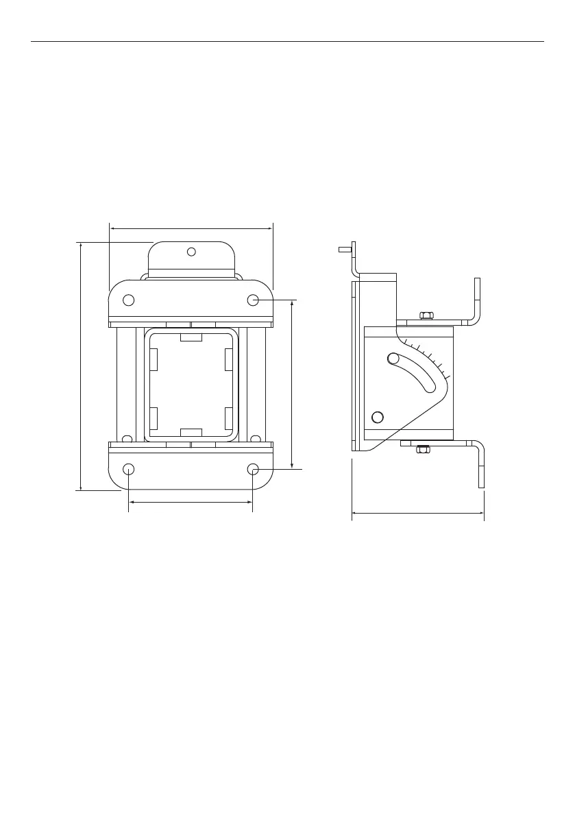
Secure the FV400 mounting bracket onto the
chosen surface at the selected location using
four M8 bolts, studs or screws at the fixing cen-
tres shown in Fig. 2. A drilling template is pro-
vided to locate the fixing centres.
Secure the detector to the bracket using the M6
stud on the bracket and two M6 bolts through
the holes at the bottom.
Fig. 2: Adjustable Mounting Bracket and Surface Mounting Dimensions
124 mm
92 mm
181 mm
122 mm
94 mm



 To Next Page