1. The fresh air intake plenum and hoods will be shipped as
an assembly on smaller cfm units. The plenums will arrive
with one set of hoods unmounted for larger cfm units.
2. The plenums and all hoods are assembled in the factory
prior to preparing for shipment. (Not all of the attachment
screws are installed in hoods that will ship unattached)
3. For those unit arriving with unattached hoods, reattach the
hoods starting with a hood in the bottom position rst. Use
the factory attached hoods as a model as well as the existing
screw holes to nalize locations.
4. When a set of detached hoods is shipped separately, one
hood will have an opening in the side for mounting the fresh
air temperature sensor. Be sure to locate this hood such that
the sensor wiring on the unit can reach this mounting location.
5. Prior to placing the hood in the mounting position, apply a
continuous bead of polyurethane caulking on the face of each
vertical hood ange and across the face of the top ange.
6. The Plenum and hood assembly can be lifted using the
lifting lugs provided on the top if the plenum
7. On the blank wall of the plenum is an access panel. This
panel can be removed to provide access to the inside of the
plenum when attaching it to the fresh air opening on the
AcuAir unit.
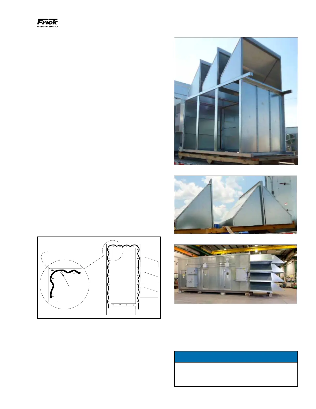
8. Apply continuous beads of polyurethane caulking on the
face of the plenum anges. The caulking should be on the
outside of the factory drilled attachment screw holes. This
caulking will prevent rain water from reaching the attachment
screw penetrations once the plenum is mounted to the AcuAir
unit. See Figure 23.
Fresh Air Plenum Caulking
Factory Drilled
Tapper
Screw Holes
Site Applied Caulk to Seal the
Plenum to the AcuAir Unit
9. Using a crane, lift the plenum with mounted hoods into
position for attaching to the AcuAir unit.
10. The two outer legs under the plenum must rest securely
on site structural supports.
11. When the plenum is plumb and level, use the screws that
were provided to attach the plenum section to the AcuAir
unit. (The screws are shipped loose and can be found in the
blower section). The predrilled holes indicated in the plenum
frame show the location and number of attachment points
required. The plenum assembly must be securely screwed to
the unit.
12. Replace the access panel, being sure that all screws are
in place.

 Loading...


