2 FS80-C Flow Switch Installation Instruction
Make all wiring connections using copper conductors only.
Use the terminal screw furnished. Substitution of other screws will void the
warranty and agency approvals.
Adjustments
To adjust the setting of the flow switch:
1. Remove the FS80-C cover.
2. For higher flow rates, turn the adjusting screw clockwise. To lower the flow
rates after it has been raised from the factory setting, turn the adjusting
screw counterclockwise. See Figure 1.
3. Check to see that the flow switch is not set lower than factory setting by
depressing the main lever numerous times. If the lever fails to “click” upon
return at any time, turn the adjusting screw clockwise until the lever clicks
upon return every time. See Figure 7.
Checkout Procedure
The circuit between the red and blue leads (terminals) will be closed when
sufficient liquid flows through the pipe to trip the flow switch.
Before leaving the installation, observe at least three complete operating
cycles to be sure that the Flow Switch and the system to which it is connected are
functioning correctly.
Table 1 Typical Flow Rate- m
3
/h Required to Actuate the Switch
a
.
Values for 2 in. paddle trimmed to fit pipe.
b
.
Values for 3 in. paddle trimmed to fit pipe.
c
.
Flow rates for these sizes are calculated installed 1 in., 2 in., 3 in. paddle. Bracket valves are for a switch with a 6 in. paddle, for 4 in. and 5 in. line pipe, the 6 in. paddle is
trimmed to a 4 in. and 5 in. length. For 8 in. line pipe, values are for install 1 in., 2 in., 3 in. and 6 in. paddle.
Table 2 Troubleshooting
Symptom/Problem Solution
Liquid from the tank is leaking into enclosure due to bellows failure.
Replace unit.
Switch will not activate due to debris caught within the switch
mechanism
Clear any debris within the switch mechanism. Test the operation of switch several times for proper
operation
Control switch action is reversed Ensure connections follow wiring diagrams
Control does not switch Check connections
Control will switch on flow but won’t return when there is no flow
On vertical pipe, ensure that direction of flow is up. The arrow on switch must point in direction of
flow (up).
Control does not switch on flow increase Check for cracked/broken paddle. Replace if necessary
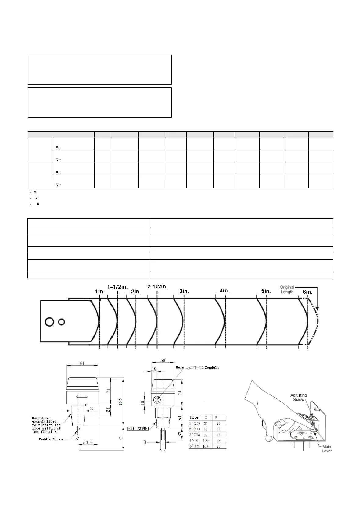
Figure 5 Trimming Template for the Extra Paddle
Figure 6 Dimensions Figure 7 Minimum Adjustment
Pipe Size(in.) 1 1-1/4
a
1-1/2
a
2 2-1/2
b
3 4
c
5
c
6
c
8
c
Flow Increase
R to B Closes
0.95 1.32 1.70 3.11 4.09 6.24
14.8
(8.4)
28.4
(12.9)
43.2
(16.8)
85.2
(46.6)
Min.
Adj.
Flow Decrease
R to Y Closes
0.57 0.84 1.14 2.16 2.84 4.32
11.4
(6.1)
22.9
(9.3)
35.9
(12.3)
72.7
(38.6)
Flow Increase
R to B Closes
2.0 3.02 4.36 6.59 7.84 12.0
29.1
(18.4)
55.6
(26.8)
85.2
(32.7)
173
(94.3)
Max.
Adj.
Flow Decrease
R to Y Closes
1.93 2.84 4.09 6.13 7.3 11.4
27.7
(17.3)
53.4
(25.2)
81.8
(30.7)
166
(90.8)
CAUTION: Equipment damage hazard
The paint sealed setpoint shall not be adjusted randomly. Any attempt
to adjust may result in failure in control and adjustment, and also it’s
out of scope of warranty.
CAUTION: Improper operation hazard
The switch is factory set at approximately the minimum flow rate (see
table 1 Typical Flow Rate). Do not set lower than the factory setting as
this may result in the switch failing to return to a “no flow” position.
 Loading...