Installation—Installing the FC-2000 59
Initiating devices requiring 24 VDC operating power can be wired as
illustrated in Figures 42 and 43.
1. The power supervision relay coil leads must be connected to the last
detector base 24V screw terminal.
2. Calculation of the maximum allowable resistance in the 24 VDC
detector power wiring:
Rmax = (20.6 - Vom)
(N)(Is) + (NA)(Ia) + (Ir)
Where:
Rmax--is the maximum resistance of the 24 V wires.
Vom--is the minimum operating voltage of the detector or end of line
relay, whichever is greater, in volts.
N--is the total number of detectors on the 24 V supply loop.
Is--is the detector current in standby.
NA--is the number of detectors on the 24 V power loop which must
function at the same time in alarm.
Ia--is the detector current in alarm.
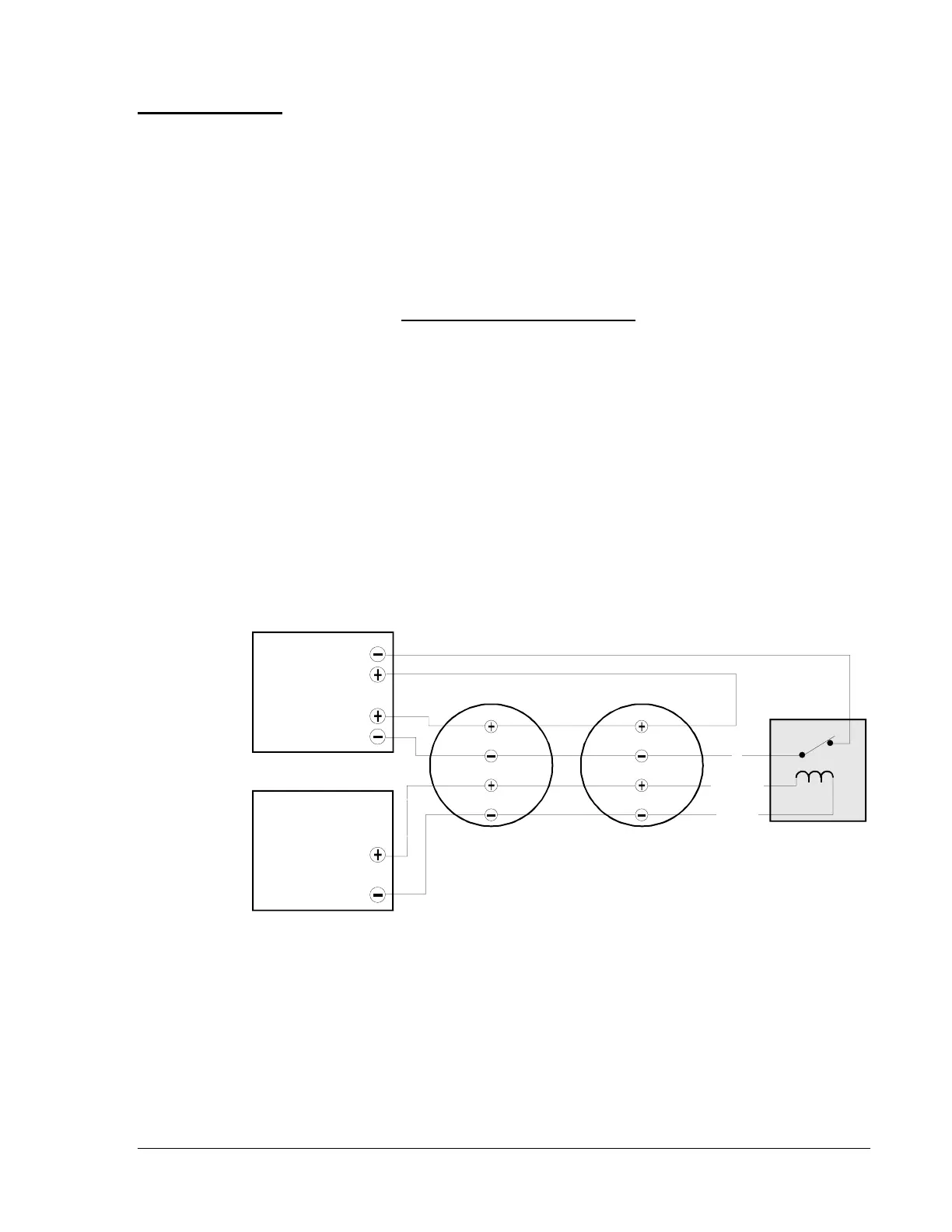
Figure 42: Employing 4-Wire Smoke Detectors (Style D)
4-Wire Smoke
Detectors
Style B and
Style D Field
Wiring
wire-d
IZM-8
Initiating Device
Circuit
MPS-24A
TB3 Term 1(+), 2(-)
24 VDC
4-Wire Detector Power
MPS-24B
TB2 Term 1(+), 2(-)
IDC(+)
IDC(-)
24 VDC(+)
Common
IDC(+)
IDC(-)
24 VDC(+)
Common
UL Listed 24 VDC
4-Wire Smoke Detectors
UL Listed
Power Supervision
Relay
C
+24 VDC
-0 VDC
NC
 Loading...

