IP-ACM v2 Ethernet Door Module features
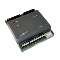
Figure 4 on Page 9 shows the switches, jumpers, ports, and connectors of the IP-ACM Ethernet Door Module v2.
Figure 4:IP-ACM Ethernet Door Module v2
Switches and jumpers
See Figure 4 on Page 9 for the locations of the switches and jumpers on the IP-ACM v2.
SW1
Table 7 on Page 9 describes the positions of switch SW1.
Position Description
SW1-1 OFF: Normal Operation
ON:Standalone Operation
Refer to the Initial Configuration section for details.
SW1-2, SW1-3, and SW1-4 Not used. Must be in the OFFposition.
Table 7:Switch SW1 descriptions
9
 Loading...