SI0270 (219)
10
JOHNSON CONTROLS
FLUSHING PROCESS FOR HYP MODEL DRIVES
System flushing is a process that is intended to drain as much of the coolant or shipping fluid as possible and dilute
this fluid in preparation for operating the drive. It is also intended to be used during annual drive servicing. The
dilution process is intended to weaken the original liquid strength to minimize any adverse effects. All fluids drained
from the drive should be collected and disposed of in accordance with local policy and regulations.
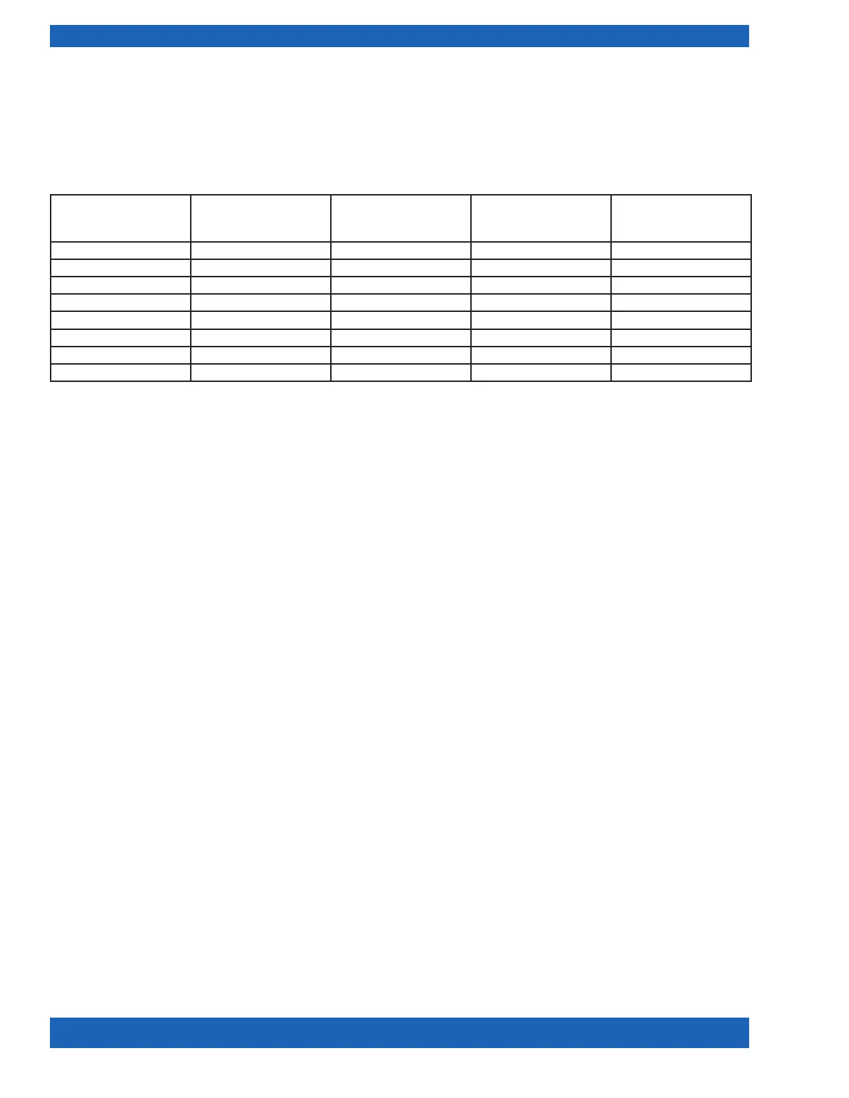
TABLE 2 - HYP DRIVE COOLANT/WATER/INHIBITOR QUANTITIES
DRIVE
MODEL
SERVICE
MANUAL
COOLANT
CAPACITY
IN GALLON
RECOMMENDED
DISTILLED
H
2
O AMOUNT
RECOMMENDED
INHIBITOR
AMOUNT
HYP0490 160.84-M3 5 15 5
HYP0612 160.84-M3 5 15 5
HYP0730 160.84-M3 6 18 6
HYP0744 160.78-M3 6 18 6
HYP0774 160.84-M3 6 18 6
HYP1100 160.00-M10 9 27 9
HYP1278 160.84-M3 9 27 9
HYP1300 160.00-M10 9 27 9
SUPPORTING DOCUMENTS
• MSDS sheets for the Inhibitor – included with shipment
• Required: Appropriate drive service manuals for 115VAC powering of the OptiView panel while the drive is
de-energized (see appropriate Table for literature form number based on the drive model).
STEP 1: Draining The System (HYP0490, HYP0744, HYP0774 Model Drives with Air-cooled Input
Inductors)
The following drain procedure applies ONLY to HYP0744, HYP0490 Mod A Drives and HYP0774 model
drives with air-cooled input inductors. See page 11 for all other HYP model drives.
If two hoses are available, the heat exchanger and the output inductor can be drained at the same time. Please see
previous diagrams for GHT locations on each drive.
1. De-energize and lockout the drive using all applicable policies and appropriate drive service literature.
2. Remove coolant reservoir cap.
3. Attach the drain hose to the GHT faucet valve on the bottom of the shell and tube heat exchanger.
4. Place the other end of the hose in a suitable container for disposal of the trapped liquid.
5. Open the heat exchanger valve to allow coolant to drain. Once coolant stops owing close the valve.
6. Attach the drain hose to the top tting of the output inductor inside the drive cabinet.
7. Place the other end of the hose in a suitable container for disposal of the trapped liquid.
8. Open the top valve of the output inductor to allow coolant to drain. Once coolant stops owing, close the valve
and remove drain hose.
9. Attach the drain hose to the bottom tting of the output inductor inside the drive cabinet.
10. Place the other end of the hose in a suitable container for disposal of the trapped liquid.
11. Open the bottom valve of the output inductor to allow coolant to drain.
12. Install coolant reservoir cap to prevent air from leaking out.

 Loading...