9 10
4
1
!
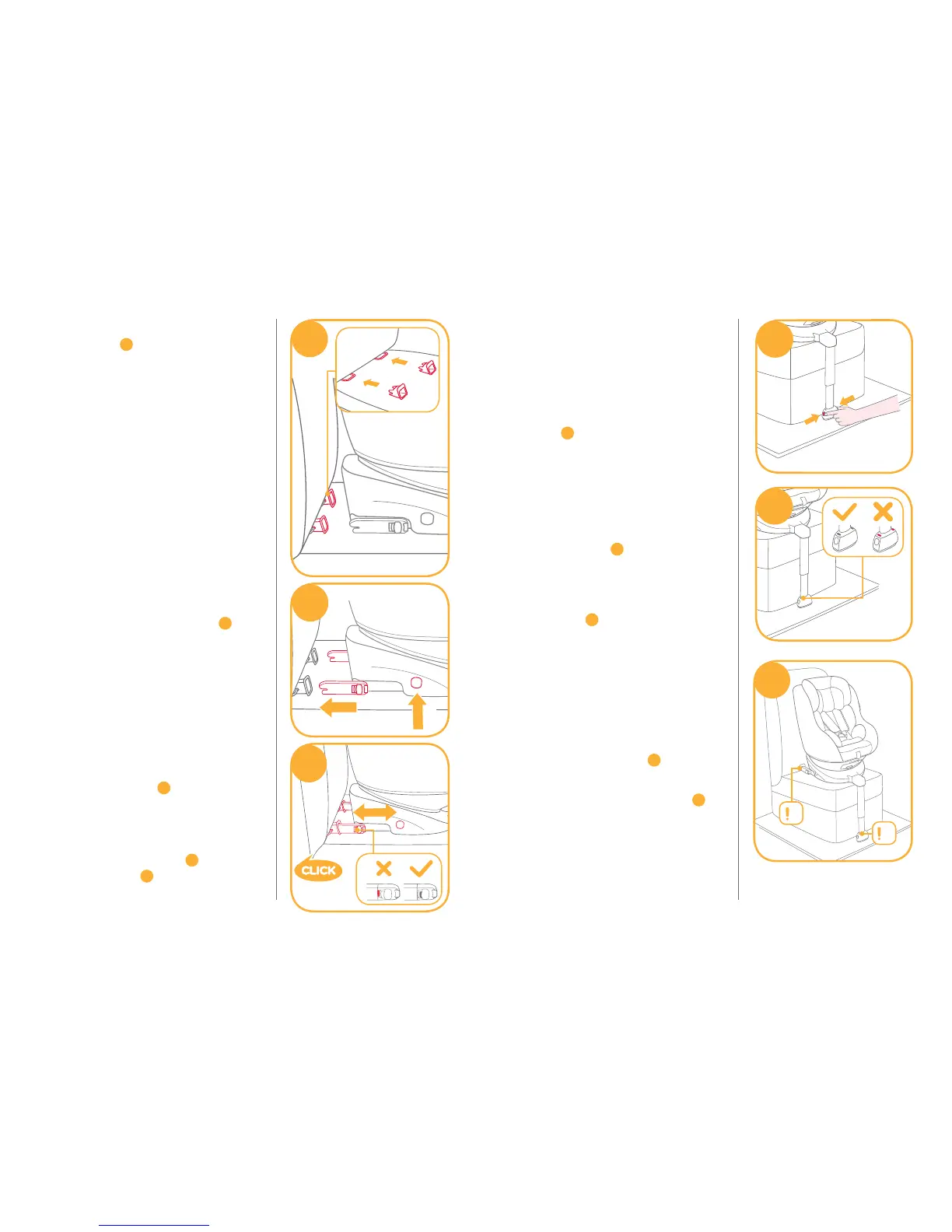
After attaching the ISOFIX, pull the
load leg downward to floor. When
the load leg indicator shows green,
the load leg is installed correctly.
!
Squeeze the load leg releasing
button, then adjust the load leg
length.
7
!
The load leg has 14 positions.
When the load leg indicator shows
red this means the load leg is in the
wrong position.
8
!
Make sure the load leg is in full
contact with the vehicle floor pan.
Red means it is installed
incorrectly.
8
!
Check to make sure the base is
securely installed by pulling on
both ISOFIX connectors.
!
The ISOFIX connectors must be
attached and locked onto the
ISOFIX anchor points.
9
-1
!
The load leg must be installed
correctly with green indicator.
9
-2
Please refer to rear facing mode and
recline positions mode in section to
use the child restraint.
7
8
9
1
2
! Insert ISOFIX guides to assist with
installation.
4
-1
! There are 10 adjustable positions for
ISOFIX. Press the ISOFIX adjuster
button to extend the ISOFIX.
5
! Make sure that both ISOFIX
connectors are securely attached to
their ISOFIX anchor points. The
colors of the indicators on both
ISOFIX connectors should be
completely green.
6
-1
! If a tighter install or increased cabin
space is required, then press the
ISOFIX adjuster button
5
-1 and
push to adjust.
6
5
1
2
1
6