www.joy-it.net
Pascalstr. 8 47506 Neukirchen-Vluyn
2. CONNECTIONS
2 multi-core cables lead out of the stepper motor.
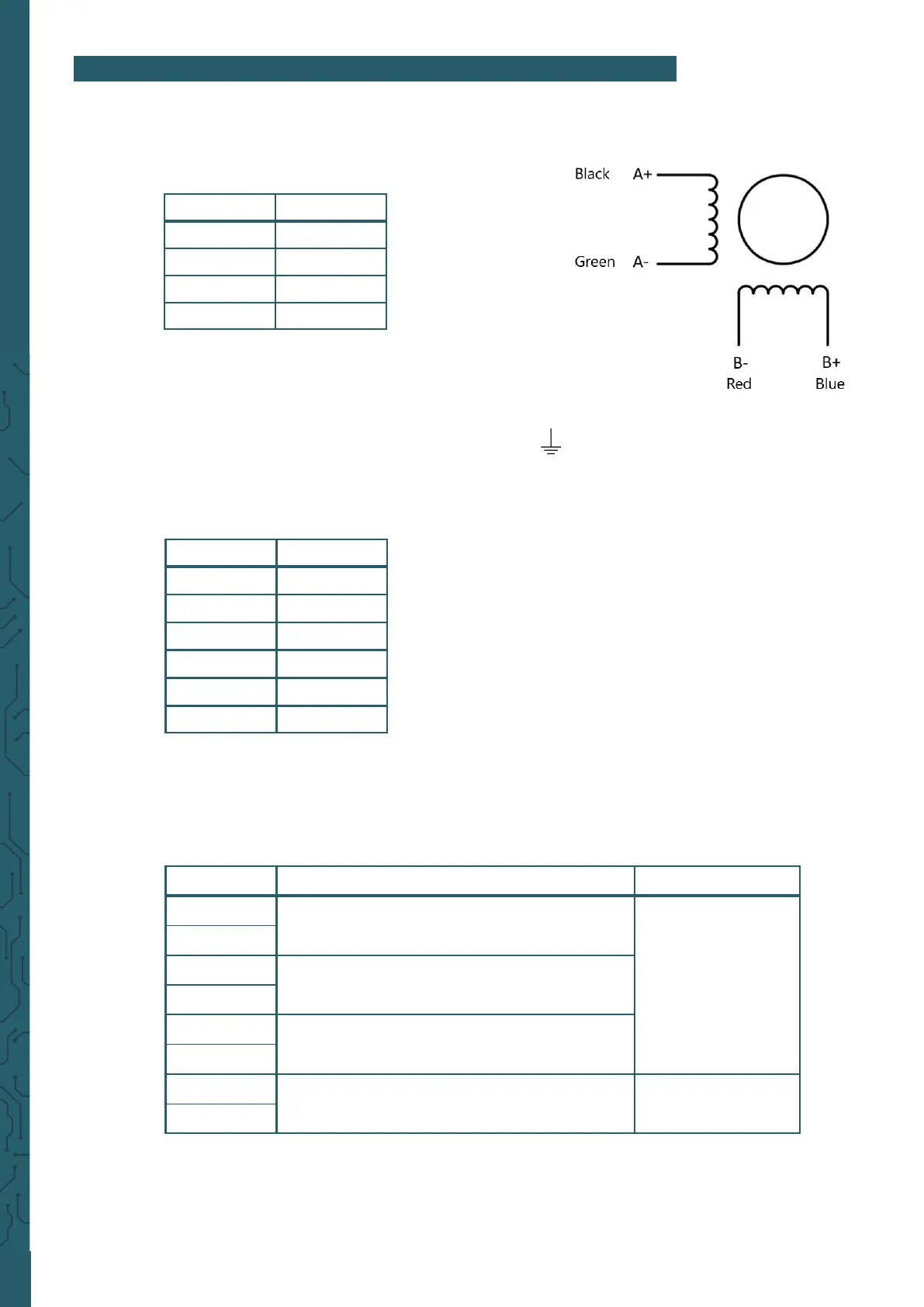
The 4-core cable belongs to the motor, the cable assignment is as follows:
In addition, an 18 - 70 V DC power supply for the motor must be connected to
the motor driver at V+ / V-.
In addition, a protective grounding can be connected to .
The 6-core cable belongs to the encoder, the cable assignment is as follows
There is another terminal block on the motor driver, this is for the control
signal.
The connections have the following functions:
Connection Colour
A+ Black
A- Green
B+ Blue
B- Red
Connection Function Remarks
PUL+
PUL+ and PUL- are the positive and negative termi-
nals of the control pulse signal.
3,3 V ~24 V
PUL-
DIR+
DIR+ and DIR- are the positive and negative terminals
of the directional signal.
DIR-
ENA+
ENA+ and ENA- the positive and negative terminals of
the enable signal.
ENA-
ALM+
ALM+ and ALM- are the positive and negative termi-
nals of the alarm output signal.
< 24 V, 40 mA
ALM-
Connection Colour
EB+ White
EB- Yellow
EA+ Green
EA- Blue
VCC Red
GND Black
 Loading...