Contents
Contents ................................................................................................................................ 1
Chapter 1 System Overview ......................................................................................... 1-1
1.1 Functions ............................................................................................................. 1-1
1.2 Features ............................................................................................................... 1-3
1.3 Scanner Units ...................................................................................................... 1-6
1.4 Transmitter Receiver Units ................................................................................ 1-9
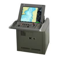
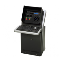
1.5 Display Units ..................................................................................................... 1-10
Chapter 2. System Configuration ................................................................................. 2-1
2.1 Components ........................................................................................................ 2-1
2.2 Power System Diagram ...................................................................................... 2-7
2.3 Function System Diagrams ............................................................................. 2-13
2.3.1 Scanner unit / transmitter-receiver unit ....................................................... 2-13
2.3.2 Display unit .................................................................................................. 2-19
2.4 I/O Specifications .............................................................................................. 2-23
2.4.1. CCU : Central Control Unit NDC-1590 I/O Specifications .......................... 2-23
2.4.2. PSU : Power Supply Unit NBD-913 I/O specifications ................................ 2-30
2.4.3. SLC : Serial LAN Interface Circuit CMH-2370 ............................................ 2-33
2.4.4. AOC : Analog Option Circuit CMJ-560 I/O specifications ......................... 2-43
2.4.5. GIF : Gyro Interface Circuit CMJ-554 I/O specifications .......................... 2-45
2.4.6. RIF :Radar Interface Circuit CQD-2273 I/O specifications.......................... 2-47
2.5 DIP-SW and Jumper Pin Settings ................................................................... 2-53
2.5.1. Setting for CQD-2273 Radar Interface Circuit............................................. 2-53
2.5.2. Settings for CMJ-554 Gyro Interface Circuit ............................................... 2-55
2.5.3. Settings for CMH-2370 Serial LAN Interface Circuit ................................... 2-59
2.5.4. Settings for CMJ-560 Analog Option Circuit ............................................... 2-72
2.5.5. Settings for NDC-1590 Central Control Unit: CCU ..................................... 2-75
2.5.6. Settings for T/R Control circuit CMC-1205R ............................................... 2-79
2.5.7. Settings for NKE-1
632 Scanner Unit ........................................................... 2-80
2.5.8. Settings for NKE-2632 Scanner Unit ........................................................... 2-81
2.5.9. Settings for NKE-2632-H Scanner Unit ....................................................... 2-82
2.5.10. Setting for UPS ............................................................................................ 2-83
2.5.11. Settings for Interswitch ................................................................................ 2-84
Chapter 3. Repair Parts .................................................................................................. 3-1
 Loading...