INSTALLATIONS
2-66
2.2.11.2 Connecting power supply and the signal lines
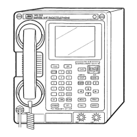
• Back of MF/HF controller (NCM-2150)
When connecting the NKG-800 printer, set the printer power of the controller to DC24V as follows.
• Back of the NKG-800
① Remove the back cover (shaded
area in diagram) and use the AF
CONT UNIT (CMV-3775) jumper pin
(TB1) to set the terminator to 2-3
side (DISP_PWR)
② Restore the cover removed at ①
so as not to catch cables.
③ Remove the cover over the printer
power source. Then connect the
printer connection cable and the
printer power cable.
After connecting the power cable,
fix it with the cable clamp and
replace the cover over the printer
power source.
DC OUT
DC6.5V
最大2A
(プリンタ専用)
6JNKD00100B
11mm
6ZCSC00407
+ -
パラレルプリンタ信号
(セントロニクスI/F)
プリンタ電源カバー
ケーブルクランプ
Printer power cover
Parallel printer signal
(Centronics I/F)
Cable clamp
DC24V
(Common to the
system power)
Power cable
Printer connection cable
TB1

 Loading...