SAFETY INSTRUCTIONS
(cont’d)
Damage requiring Service
Unplug this product from the wall outlet and refer
servicing to qualified service personnel under the
following conditions:
(a) When the power-supply cord or plug is
damaged.
(b) If liquid has been spilled, or objects have
fallen into the product.
(c) If the product has been exposed to rain or
water.
(d) If the product does not operate normally by
following the operating instructions.
Adjust only those controls that are covered
by the operating instructions as an improper
adjustment of other controls may result in
damage and will often require extensive work
by a qualified technician to restore the pro-
duct to its normal operation.
(e) If the product has been dropped or the
cabinet has been damaged.
(f) When the product exhibits a distinct change
in performance — this indicates a need for
service.
Replacement Parts
When replacement parts are required, be sure the
service technician has used replacement parts
specified by the manufacturer that have the same
characteristics as the original part. Unauthorized
substitutions may result in fire, electric shock or
other hazards.
External Load
Connect the DC motor rated at 24 VDC, 2A
(48W), or less to the product. Operate the pulse
encoder at the load of 24 VDC, 0.5A (1 2W), or
less.
External Cables
Connect the cables with VW-1 rated jacket to the
product. Cables consisted of wires suitable for
the rating of the intended load should be used.
Otherwise, use the cables specified by the
manufacturer.
Installation
This installation should be made by a qualified
service person and should conform to all local
codes.
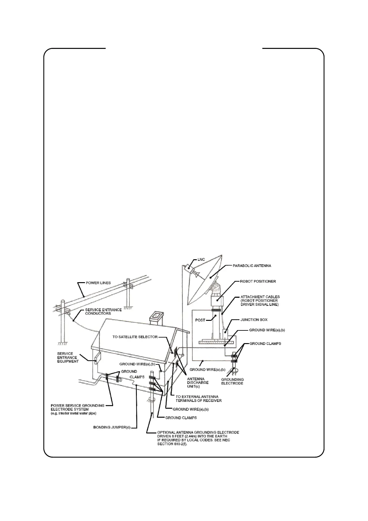
Outdoor Antenna Grounding
If an outside antenna or cable system is con-
nected to the product, be sure the antenna or
cable system is grounded so as to provide some
protection against voltage surges and built-up
static charges. Section 810 of the National Elec-
trical Code, ANSI/NFPA No. 70— 1 984, provides
information with respect to proper grounding of
the mast and supporting structure, grounding of
the lead-in wire to an antenna discharge unit, size
of grounding conductors, location of antenna-
discharge unit, connection to grounding elec-
trodes, and requirements for the grounding elec-
trode. See Figure 1.
FIGURE 1
EXAMPLE OF ANTENNA GROUNDING ACCORDING TO
NATIONAL ELECTRICAL CODE INSTRUCTIONS
CONTAINED IN ARTICLE 810 - „RADIO AND TELEVISION
EQUIPMENT”
2
(a) Use No. 10 AWG (5.3 mm )
2
copper, No. 8 AWG (8.4 mm )
a l u m i n u m , N o . 1 7 A W G
2
(1.0 mm ) copper-clad steel or
bronze wire, or larger, as a
ground wire.
(b) Secure antenna lead-in and
ground wires to house with
stand-off insulators spaced
from 4 - 6 feet (1.22 - 1.83 m)
apart.
(c) Mount antenna discharge unit
as close as possible to where
lead-in enters house.
(d) Use jumper wire not smaller
2
than No. 6 AWG (13.3mm )
copper, or the equivalent, when
a separate antenna-grounding
electrode is used. See NEC Sec-
tion 810-21 (j).
 Loading...