Do you have a question about the JUMO iTRON B 70.2040 and is the answer not in the manual?
Describes the bezel size of the instrument.
Details configurable controller types and customer specifications.
Specifies configurable input options and settings.
Outlines standard and optional output configurations.
Details the available power supply options for the instrument.
Describes additional functions available via extra codes.
Lists the components included in the instrument's delivery package.
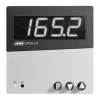
Details the instrument's display segments and front panel buttons.
Explains the different operating levels and states of the controller.
Describes how to start, stop, and manage the timer function.
Details how to configure the input for process value measurement.
Explains the functionality and configurations for the logic input.
Defines controller structure and parameters like proportional band, derivative, and reset time.
Describes the limit comparator function and its configurations.
Explains the ramp function, its parameters, and timing.
Details the self-optimization process for PID/PI controller parameters.
Explains how to set level inhibit using a code as an alternative to logic input.
Describes how the timer function influences control actions and its parameters.
Defines controller types and output assignments.
Lists configurations for the limit comparator function.
Details ramp function settings and time units.
Specifies output behavior during fault conditions.
Defines the functions assigned to the logic input.
Details output assignments for relay and logic types across configurations.
Defines various timer functions like time-limited and time-dependent.
Specifies events that trigger timer start and power failure actions.
Describes how to configure timer signalling via outputs.
Sets the time unit for timer operations (mm.ss, hh.mm, hhh.h).
| Type | Compact controller |
|---|---|
| Housing | Plastic |
| Output | Relay, analog |
| Display | 4-digit LED display |
| Power Supply | 24 V AC/DC |
| Communication | RS485 |
| Protection | IP65 (front) |
| Operating Temperature | -10 to 55 °C |
| Storage Temperature | -20 to +70 °C |