4. Place the grounding cable lug over the grounding points on the bottom rear of the
chassis. The top pair is sized for M6 screws, and the bottom pair is sized for UNC 1/4-20
screws. You can use either pair of grounding points. UNC 1/4-20 screws are provided
in the accessory kit.
5. Secure the grounding cable lug to the grounding points, first with the washers, then
with the screws.
6. Verify that the grounding cabling is correct, that the grounding cable is not touching
or blocking access to the packet transport switch components, and that it does not
drape where people could trip on it.
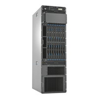
Figure 38: Connecting the Grounding Cable
Related
Documentation
• PTX5000 Chassis Description on page 12
• Tools and Parts Required to Ground the PTX5000 Packet Transport Switch on page 83
Copyright © 2012, Juniper Networks, Inc.84
PTX5000 Packet Transport Switch Hardware Guide

 Loading...