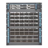
Figure 70: Clearance Requirements for Airflow and Hardware Maintenance for a PTX10016 Chassis
g050723
Clearan ce requi red
for main t enan ce
19"
(4 8 .3 cm)
32"
(81 .3 cm)
35 "
(88 .9 cm)
for main t enan ce
Clearan ce requi red
Front mounting flange
24 " ( 6 1cm) 24 " ( 6 1cm)
FRUs
Ports
17.4"
3" (7.6 cm)
4 " (10.2 cm)
Power cable depth
5.1" (13 cm.)
Cable management depth
6.1" (15.5 cm.)
Front panel depth
12" (30.5 cm)
For airflow
(4 4.2 cm)
(Mounting
flange width)
12" (30.5 cm.)
For airflow
Figure 71: Clearance Requirements for Airflow and Hardware Maintenance for a PTX10016 with
JNP10008-FAN2
g100683
Ports
Clearance required
for maintenance
19 in.
(48.3 cm)
(Mounting
flange width)
24 in (61 cm)
FRUs
Clearance required
for maintenance
17.4 in.
(44.2 cm)
36.7 in.
(93.2 cm)
35 in.
(88.9 cm)
34.2 in.
(86.8 cm)
30 in. (76.2 cm)
Follow these guidelines:
•
For the cooling system to function properly, the airflow around the chassis must be unrestricted. See
“PTX10008 Cooling System and Airflow” on page 46 and PTX10016 Cooling System for more information
about the airflow through the chassis.
•
If you are mounting a PTX10000 in a rack with other equipment, ensure that the exhaust from other
equipment does not blow into the intake vents of the chassis.
•
Leave at least 24 in. (61 cm) both in front of and behind the PTX10000 for service personnel to remove
and install hardware components. To be NEBS GR-63 compliant, allow at least 30 in. (76.2 cm) in front
of the rack and 24 in. (61 cm) behind the rack.
158

 Loading...