Do you have a question about the JVC AV-29MT16/Z and is the answer not in the manual?
General safety guidelines for service and product handling, emphasizing manufacturer recommendations.
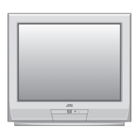
Step-by-step instructions for disassembling specific models, covering rear cover, speakers, and boards.
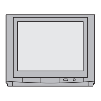
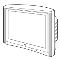
Disassembly steps for larger models, including chassis, AV terminal, control base, and speakers.
Instructions for replacing the memory IC, including power off/on and system constant settings.
Detailed steps for removing and installing chip components, with cautions and soldering iron tips.
Steps and equipment needed for performing adjustments using the remote or test equipment.
Comprehensive list of all adjustable parameters covering B1 voltage, IF, video, deflection, and audio circuits.
Explains how to enter, select submenus, and set values within the Service Menu.
Procedure for adjusting the focus VR on the HVT to achieve a clear picture.
Procedures for IF VCO check and DELAY POINT adjustment to eliminate noise.
Procedure for demagnetizing CRT and adjusting purity magnets and deflection yoke for proper convergence.
Overview of self-check functions, how abnormalities are detected, and power off indication.
Explanation of symbols, abbreviations, and notations used in circuit diagrams.
Overall system block diagram illustrating the interconnection of major functional units.
Detailed circuit diagram for the main PWB, covering specific sections.
Visual layout of components and traces on the main PWB for specific models.
Table listing voltage measurements at key points on various PWB assemblies.
Illustrations of typical waveforms measured on the main PWB for troubleshooting.
Safety cautions for replacing parts, emphasizing the use of specified components.
Parts identification for the first exploded view of the TV chassis.
Parts identification for the first exploded view of the AV-25MT16/Z model.
Parts identification for the first exploded view of AV-29MT16/Z and AV-29MT36/Z.