1-14 (No.MB433)
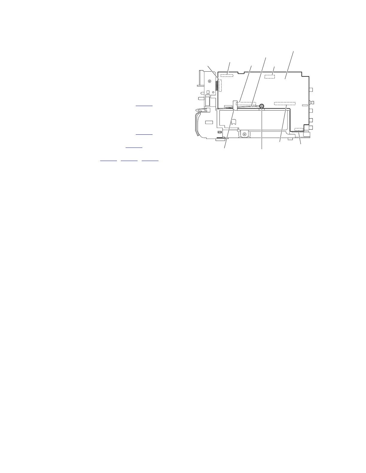
3.1.9 Removing the micom board
(See Fig.23)
• Remove the side panels L/R, top panel assembly and rear
panel.
(1) From the right side of the main body, remove the screw S
attaching the micom board.
Reference:
• When attaching the screw S, attach the earth wire with
it.
• After attaching the earth wire, fix it with the spacer as
before.
(2) Disconnect the card wire from the connector CN421
on the
forward side of the micom board.
Reference:
Remove the tuner as required. (See Figs.10 and 11.)
(3) Disconnect the card wire from the connector CN426
on the
forward side of the micom board.
(4) Disconnect the wire from the connector CN501
on the for-
ward side of the micom board.
(5) Disconnect the connectors (CN423
, CN424, CN425) on
the micom board from the regulator and video boards to-
ward this side to remove the micom board.
Fig.23
CN421
CN426
CN424
CN501
Micom board
Earth wire
Spacer
CN423
CN425
S
 Loading...