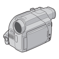
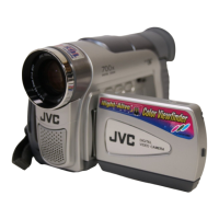
This document serves as a service manual for a range of JVC digital video cameras, including models GR-DF420EK, GR-DF420EX, GR-DF420EY, GR-DF420EZ, GR-DF425EK, GR-DF425EG, GR-DF430EK, GR-DF460EK, GR-DF470EK, GR-DF470EX, GR-DF470EY, and GR-DF470EZ. It provides detailed information for servicing these camcorders, covering specifications, safety precautions, disassembly/assembly procedures, adjustment guidelines, and troubleshooting.
The primary function of these devices is digital video recording, with some models also offering digital still camera capabilities. They operate on the Mini DV cassette format, recording video in PAL standard digital component format and audio in PCM digital recording (32 kHz 4-channel 12-bit or 48 kHz 2-channel 16-bit).
Key technical specifications include:
- Power Supply: DC 11.0 V (using AC Adapter) or DC 7.2 V (using battery pack).
- Power Consumption: Approximately 3.2 W (LCD monitor off, viewfinder on) and 4.2 W (LCD monitor on, viewfinder off). Models with an LED Light consume slightly more.
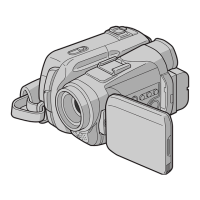
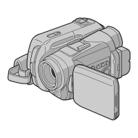
- Dimensions: 75 mm (W) × 74 mm (H) × 111 mm (D) with the LCD monitor closed and viewfinder pushed back.
- Weight: Approximately 400g (without battery, cassette, memory card, and lens cap), increasing to about 480g with these accessories. GR-DF430, GR-DF460, and GR-DF470 models are slightly heavier.
- Operating Temperature: 0°C to 40°C.
- Operating Humidity: 35% to 80%.
- Storage Temperature: -20°C to 50°C.
- Pickup: 1/6" CCD.
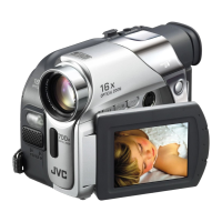
- Lens: F 1.2, f = 2.6 mm to 39 mm, 15:1 power zoom lens.
- Filter Diameter: Ø30.5 mm.
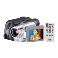
- LCD Monitor: 2.5" diagonally measured, TFT active matrix system.
- Viewfinder: Electronic viewfinder with 0.16" color LCD.
- Speaker: Monaural.
- LED Light: Effective distance: 1.5 m (for LED Light models only).
- Tape Speed: SP: 18.8 mm/s, LP: 12.5 mm/s.
- Maximum Recording Time: SP: 80 min., LP: 120 min. (using 80 min. cassette).
- Digital Still Camera (GR-DF460, GR-DF470 only):
- Storage Media: SD Memory Card/MultiMediaCard.
- Compression System: JPEG (compatible).
- File Size: Still image: 2 modes (1024 × 768 pixels/640 × 480 pixels); Moving image: 1 mode (160 × 120 pixels).
- Picture Quality: 2 modes (FINE/STANDARD).
- Connectors:
- S-Video Input (GR-DF430, GR-DF470 only): Y: 0.8-1.2 V (p-p), 75Ω, analogue; C: 0.2-0.4 V (p-p), 75Ω, analogue.
- S-Video Output: Y: 1.0 V (p-p), 75Ω, analogue; C: 0.29 V (p-p), 75Ω, analogue.
- AV Video Input (GR-DF430, GR-DF470 only): 0.8-1.2 V (p-p), 75Ω, analogue.
- Video Output: 1.0 V (p-p), 75Ω, analogue.
- Audio Input (GR-DF430, GR-DF470 only): 300 mV (rms), 50 kΩ, analogue, stereo.
- Audio Output: 300 mV (rms), 1 kΩ, analogue, stereo.
- Microphone Input: Ø3.5 mm, stereo.
- DV Input/Output (GR-DF430, GR-DF460, GR-DF470 only): 4-pin, IEEE 1394 compliant.
- USB (GR-DF460, GR-DF470 only): Mini USB-B type, USB 1.1/2.0 compliant.
- AC Adapter: Power requirement: AC 110-240 V, 50/60 Hz; Output: DC 11 V, 1 A.
Usage features are primarily related to connectivity and model-specific functionalities. For instance, some models include an LED light, memory card slot, USB terminal, DV input/output, and analog input, while others do not. Remote control compatibility also varies by model. The service manual highlights these differences in a dedicated list.
Maintenance features are extensively covered, emphasizing safety and precision during servicing.
- Safety Precautions: Critical components are marked with a "!" symbol and shaded, requiring replacement only with specified parts. Fuse replacement must use the same type and rating. Wiring and insulating materials must be handled carefully to prevent hazards. Proper screw tightening torque (0.069 N·m or 0.7 kgf·cm, unless specified) is crucial.
- Tools Required: A torque driver, specific bits, tweezers, a chip IC replacement jig, and a cleaning cloth are recommended.
- Disassembly/Assembly: Detailed step-by-step instructions are provided for disassembling and assembling various parts, including the cabinet, electrical components, upper assembly (viewfinder, monitor, monitor operation board), OP block assembly (CCD board, focus/zoom/auto iris motor units), and VF assembly (LCD assembly, lens assembly). Specific notes guide technicians on handling fragile parts like FPCs, avoiding damage, and ensuring correct positioning.
- Cleaning: Fine-woven cotton cloth with alcohol is recommended for cleaning video heads, tape transport systems, and optical lens surfaces.
- Applying Oil and Grease: Periodical oiling and greasing are specified for new parts, with instructions to clean old parts before application.
- Adjustments: Electrical adjustments require a personal computer with SERVICE SUPPORT SYSTEM software, a color TV monitor, oscilloscope, digital voltmeter, and frequency counter. Special tools like INF adjustment lenses, a camera stand, light box assembly, gray scale chart, and color bar chart are used for camera system adjustments. Mechanism compatibility adjustments, such as tape pattern adjustment, are also detailed, involving observation of waveforms and turning guide rollers to achieve flatness.
- Troubleshooting: The manual includes a section on emergency display error codes (e.g., E01 for loading issues) and their possible causes, such as mechanism lock, power supply problems, or tape transport issues. It also provides detailed voltage charts for various ICs and transistors in both REC and PLAY modes, aiding in diagnostic procedures.
The manual also contains detailed schematic diagrams for the main board, audio, DSC, USB, reel, CCD, MDA, front, monitor operation, monitor BL, and VF circuits, along with exploded views and parts lists for various assemblies. These resources are essential for identifying components, understanding circuit layouts, and performing accurate repairs.