TABLE OF CONTENTS
Section Title Page Section Title Page
2.2.24 Rotor assembly ........................................................... 2-14
2.2.25 Upper drum assembly ................................................. 2-15
2.3 Compatibility adjustment .................................................... 2-16
2.3.1 FM waveform linearity ................................................... 2-16
2.3.2 Height and tilt of the A/C head ....................................... 2-17
2.3.3 A/C head phase (X-value) ............................................. 2-17
2.3.4 Standard tracking preset ............................................... 2-18
2.3.5 Tension pole position ..................................................... 2-18
3. ELECTRICAL ADJUSTMENT
3.1 Precaution ............................................................................ 3-1
3.1.1 Required test equipments ............................................... 3-1
3.1.2 Required adjustment tools ............................................... 3-1
3.1.3 Color (colour) bar signal, color (colour) bar pattern ......... 3-1
3.1.4 Switch settings and standard precautions ....................... 3-1
3.2 Servo circuit .......................................................................... 3-2
3.2.1 Switching point ................................................................ 3-2
3.2.2 Slow tracking preset ........................................................ 3-2
3.3 Video circuit .......................................................................... 3-2
3.3.1 Auto picture initial setting ................................................ 3-2
3.4 Syscon circuit [HR-J680EU/J780EU] ................................... 3-2
3.4.1 Timer clock ...................................................................... 3-2
4. CHARTS AND DIAGRAMS
NOTES OF SCHEMATIC DIAGRAM .......................................... 4-1
CIRCUIT BOARD NOTES ........................................................... 4-2
4.1 BOARD INTERCONNECTIONS .......................................... 4-3
4.2 MAIN(VIDEO/AUDIO) SCHEMATIC DIAGRAM ................... 4-5
4.3 MAIN(ON SCREEN) SCHEMATIC DIAGRAM ..................... 4-7
4.4 MAIN(SYSCON) SCHEMATIC DIAGRAM ........................... 4-9
4.5 MAIN(SW.REG) SCHEMATIC DIAGRAM ...........................4-11
4.6 MAIN(TUNER) SCHEMATIC DIAGRAM ............................ 4-13
4.7 MAIN(FRONT) AND ADV.JOG SCHEMATIC DIAGRAMS . 4-15
4.8 MAIN(TERMINAL), SAT CTL AND R.PAUSE SCHEMATIC
DIAGRAMS ........................................................................ 4-17
4.9 REMOTE CONTROLLER SCHEMATIC DIAGRAM ........... 4-19
4.10 MAIN, SAT CTL AND R.PAUSE CIRCUIT BOARDS ....... 4-21
4.11 FDP GRID ASSIGNMENT AND ANODE CONNECTION 4-23
4.12 WAVEFORMS .................................................................. 4-24
4.13 VOLTAGE CHARTS ......................................................... 4-25
4.14 CPU PIN FUNCTION ....................................................... 4-26
4.15 SYSTEM CONTROL BLOCK DIAGRAM ......................... 4-27
4.16 VIDEO BLOCK DIAGRAM ............................................... 4-29
4.17 AUDIO BLOCK DIAGRAM .............................................. 4-31
5. PARTS LIST
5.1 PACKING AND ACCESSORY ASSEMBLY <M1> ............... 5-1
5.2 FINAL ASSEMBLY <M2> .................................................... 5-2
5.3 MECHANISM ASSEMBLY <M4> ........................................ 5-4
5.4 ELECTRICAL PARTS LIST .................................................. 5-6
MAIN BOARD ASSEMBLY <03> ............................................... 5-6
A/C HEAD BOARD ASSEMBLY <12> ..................................... 5-13
ADV.JOG BOARD ASSEMBLY(HR-J780EU/J785EK) <38> ... 5-13
LOADING MOTOR BOARD ASSEMBLY <55> ....................... 5-13
R.PAUSE BOARD ASSEMBLY(HR-J780EU)<91> ................. 5-13
SAT_CTL BOARD ASSEMBLY <92> ...................................... 5-13
Important Safety Precautions
INSTRUCTIONS
1. DISASSEMBLY
1.1 Disassembly flow chart ......................................................... 1-1
1.2 How to read the disassembly and assembly ........................ 1-1
1.3 Disassembly/assembly method ............................................ 1-1
1.4 Service position .................................................................... 1-4
1.4.1 How to set the “Service position” ..................................... 1-4
1.5 Mechanism service mode ..................................................... 1-4
1.5.1 How to set the “Mechanism service mode” ..................... 1-4
1.6 Jig RCU mode ....................................................................... 1-4
1.6.1 Setting the Jig RCU mode ............................................... 1-4
1.6.2 Setting the User RCU mode ............................................ 1-4
1.7 Emergency display function ................................................. 1-5
1.7.1 Displaying the EMG information ...................................... 1-5
1.7.2 Clearing the EMG history ................................................ 1-5
1.7.3 EMG content description ................................................. 1-6
1.7.4 EMG detail information <1> ............................................. 1-7
1.7.5 EMG detail information <2> ............................................. 1-8
2. MECHANISM ADJUSTMENT
2.1 Before starting repair and adjustment ................................... 2-1
2.1.1 Precautions ..................................................................... 2-1
2.1.2 Checking for proper mechanical operations .................... 2-1
2.1.3 Manually removing the cassette tape .............................. 2-1
2.1.4 Jigs and tools required for adjustment ............................ 2-2
2.1.5 Maintenance and inspection ............................................ 2-3
2.2 Replacement of major parts ................................................. 2-6
2.2.1 Before starting disassembling (Phase matching between
mechanical parts) ............................................................ 2-6
2.2.2 How to set the “Mechanism assembling mode” .............. 2-6
2.2.3 Cassette holder assembly ............................................... 2-6
2.2.4 Pinch roller arm assembly ............................................... 2-8
2.2.5 Guide arm assembly and press lever assembly .............. 2-8
2.2.6 A/C head ......................................................................... 2-8
2.2.7 Loading motor ................................................................. 2-8
2.2.8 Capstan motor ................................................................. 2-9
2.2.9 Pole base assembly (supply or take-up side) .................. 2-9
2.2.10 Rotary encoder ........................................................... 2-10
2.2.11 Clutch unit ................................................................... 2-10
2.2.12 Change lever assembly, direct gear, clutch gear and
coupling gear .............................................................. 2-10
2.2.13 Link lever ..................................................................... 2-11
2.2.14 Cassette gear, control cam and worm gear .................2-11
2.2.15 Control plate ................................................................ 2-11
2.2.16 Loading arm gear (supply or take-up side) and
loading arm gear shaft ................................................ 2-12
2.2.17 Take-up lever, take-up head and control plate guide .. 2-13
2.2.18 Capstan brake assembly ............................................ 2-13
2.2.19 Sub brake assembly (take-up side) ............................ 2-13
2.2.20
Main brake assembly (take-up side), reel disk (take-up side)
and main brake assembly (supply side) ................................
2-13
2.2.21 Tension brake assembly, reel disk (supply side) and
tension arm assembly ................................................. 2-14
2.2.22 Idler lever, idler arm assembly .................................... 2-14
2.2.23 Stator assembly .......................................................... 2-14
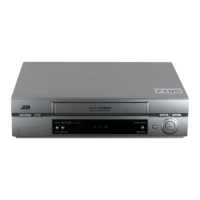
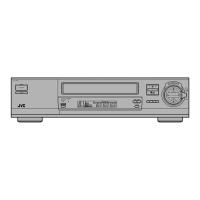
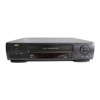
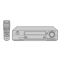
HR-J680EK HR-J680EU HR-J780EU HR-J785EK
JOG/SHUTTLE NOT USED NOT USED USED USED
VIDEO SYSTEM PAL PAL/MESECAM(MANUAL) PAL/MESECAM(MANUAL) PAL
BROADCASTING STANDARD I B/G,D/K B/G,D/K I
STEREO DECODER NICAM NICAM/A2 NICAM/A2 NICAM
RF OUT SYSTEM [INITIAL] I G,K G,K I
VCR PLUS+ VIDEOPLUS+ DELUXE SHOWVIEW DELUXE SHOWVIEW DELUXE VIDEOPLUS+ DELUXE
LANGUAGE [INITIAL] (ON SCREEN DISPLAY)
ENG 13LANG.[ENG] 13LANG.[ENG] ENG
AUDIO DUBBING/OPERATION NOT USED NOT USED USED/BUTTON NOT USED
FRONT VIDEO/AUDIO IN NOT USED NOT USED USED NOT USED
WINDOW COLOR SMOKE LIGHT GRAY SMOKE LIGHT GRAY BLUE SMOKE LIGHT GRAY
REMOTE PAUSE NOT USED NOT USED USED NOT USED
CABLE MOUSE PROVIDED OPTION OPTION PROVIDED
The following table lists the differing points between Models ( HR-J680EK, HR-J680EU, HR-J780EU and HR-J785EK) in this series.
 Loading...