EasyManua.ls Logo

JVC HR-J595MS User Manual

JVC HR-J595MS
90 pages
To Next Page IconTo Next Page
Page #1 background imageLoading...
Page #1 background image
SERVICE MANUAL
No.82915
June 2002
HR-J282EU, HR-J283EU, HR-J285EU,
HR-J290EU, HR-J293EU, HR-J295EK, HR-J295MS,
HR-J582EU, HR-J583EU, HR-J585EU,
HR-J590EU, HR-J593EU, HR-J595EK, HR-J595MS
VIDEO CASSETTE RECORDER
SPECIFICATIONS
(The specifications shown pertain specifically to the model HR-J290EU, J293EU, J590EU and J593EU.)
This service manual is printed on 100% recycled paper.
COPYRIGHT © 2002 VICTOR COMPANY OF JAPAN, LTD
V15
Specifications shown are for SP mode unless specified otherwise.
E. & O.E. Design and specifications subject to change without
notice.
GENERAL
Power : 200 V – 240 V , 50 Hz/60 Hz
Power consumption
Power on : Approx. 12 W
Standby mode : 3.0 W
Video Head system
HR-J590/J593/
J599EU
: DA4 (Double Azimuth) head helical
scan system
HR-J290/J293EU : Rotary two-head helical scan system
Tape speed
(SP) : 23.39 mm/sec
(LP)* : 11.69 mm/sec
* HR-J590/J593/J599EU only
Tape format : Tape width 1/2"
(12.7 mm high density VHS tape)
Maximum recording time
(SP) : 240 min. with E-240 video cassette
(LP)* : 480 min. with E-240 video cassette
* HR-J590/J593/J599EU only
Rewind time : Approx. 180 sec. with E-180 cassette
Dimensions (W x H x D) : 360 mm x 94.5 mm x 270 mm
Weight : 4.0 kg
Operating temperature : 5°C to 35°C
Operating humidity : Less than 80 %
Timer : 24 hours display type
VIDEO
Signal system : PAL-type colour signal and CCIR
monochrome signal, 625 lines
50 fields
Recording Format : PAL/MESECAM
RF reception : PAL (B/G)/SECAM (B/G)
RF OUT : PAL G
RF modulator : UHF channels 22 – 68 (Adjustable)
Input level : VIDEO IN (SCART type)
1.0 Vp-p, 75 ohm, unbalanced
Output level : VIDEO OUT (SCART type)
1.0 Vp-p, 75 ohm, unbalanced
Signal-to-noise ratio : More than 43 dBm
AUDIO
Input level : AUDIO IN (SCART type)
–6.0 dBm, more than 10 k
Output level
HR-J590/J593/
J599EU
: AUDIO OUT (SCART, RCA type)
–6.0 dBm, less than 1 k
HR-J290/J293EU : AUDIO OUT (SCART type)
–6.0 dBm, less than 1 k
Audio track
HR-J590/J593/
J599EU
: Mono track and Hi-Fi track
HR-J290/J293EU : Mono track
Audio frequency response
Normal audio : 100 Hz to 10,000 Hz
(–6/+3 dBm)
Hi-Fi audio* : 20 Hz to 20,000 Hz
(–3/+3 dBm)
* HR-J590/J593/J599EU only
Audio signal to noise ratio [HR-J590/J593/J599EU only]
Hi-Fi audio : More than 70 dB (JIS A filter)
Audio dynamic range [HR-J590/J593/J599EU only]
Hi-Fi audio : More than 85 dB (JIS A filter)
ACCESSORIES
Provided accessories : RF cable,
Infrared remote control unit,
“R3” battery x 2
Question and Answer IconNeed help?

Do you have a question about the JVC HR-J595MS and is the answer not in the manual?

JVC HR-J595MS Specifications

General IconGeneral
TypeVCR
Recording FormatVHS
TunerYes
Remote ControlYes
Heads4
Hi-Fi AudioYes
ShowViewYes
Playback FormatsVHS
ConnectionsRF
InputsComposite video
OutputsSCART, RF
Dimensions360 x 97 x 232 mm

Summary

SECTION 1 SUMMARY

KEY TO ABBREVIATIONS

Glossary of technical acronyms and terms used in the manual.

IMPORTANT SAFETY PRECAUTIONS

Critical safety guidelines for handling and servicing the equipment.

PROPOSAL FOR APPLYING SHORT PROTECTION

Method to implement short-circuit protection for ICs to prevent overheating.

SERVICE NOTICE ON REPLACING EEPROM

Instructions for initializing EEPROM after replacement for PAL models.

SERVICE INFORMATION FOR EEPROM IC SETTING

Detailed procedure for setting EEPROM option codes based on model variations.

SPECIFICATIONS

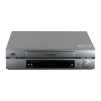
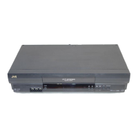
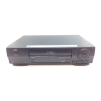
Comprehensive technical specifications for the video cassette recorder.

SECTION 2 CABINET & MAIN CHASSIS

SERVICE METHOD

Procedures for servicing the electrical parts and re-assembly flow.

EXPLODED VIEWS

Visual diagrams illustrating the breakdown of the unit's main chassis and frame.

SECTION 3 ELECTRICAL

ELECTRICAL ADJUSTMENT POINTS ARRANGEMENT

Diagram showing measurement and adjustment points within the electrical system.

ELECTRICAL ADJUSTMENT PROCEDURES

Step-by-step instructions for performing electrical adjustments, like servo calibration.

ELECTRICAL TROUBLESHOOTING GUIDE

Flowcharts to diagnose and resolve electrical faults in the power and servo circuits.

SECTION 4 MECHANISM

DECK MECHANISM PARTS LOCATIONS

Identification and location of various parts within the tape deck mechanism.

DECK MECHANISM DISASSEMBLY

Detailed instructions for disassembling the tape deck mechanism component by component.

DECK MECHANISM ADJUSTMENT

Procedures for adjusting critical mechanism settings like torque, height, and alignment.

MAINTENANCE/INSPECTION PROCEDURE

Guidelines for routine maintenance, cleaning, lubrication, and inspection of the unit.

MECHANISM TROUBLESHOOTING GUIDE

Diagnostic flowcharts to identify and resolve common mechanism operational failures.

BLOCK DIAGRAMS

Power Block Diagram

Schematic representation of the power supply circuit and its components.

Tuner/IF, NICAM & A2 Block Diagram

Block diagram showing the tuner, IF, NICAM, and A2 signal processing paths.

VPS Block Diagram

Block diagram illustrating the Video Programming System (VPS) signal path.

Y/C Block Diagram

Block diagram detailing the Y (Luminance) and C (Chrominance) signal paths.

Hi-Fi Block Diagram

Block diagram for the Hi-Fi audio signal processing within the unit.

System Block Diagram

Overall system block diagram showing the interaction of major functional units.

CIRCUIT DIAGRAMS

Power Circuit Diagram

Detailed schematic of the power supply circuit, including component values.

Tuner, NICAM Circuit Diagram

Schematic of the tuner, NICAM, and A2 audio circuits.

A/V, SECAM, VPS Circuit Diagram

Circuit diagram for Audio/Video, SECAM, and VPS signal processing.

System Circuit Diagram

Comprehensive circuit diagram of the main system control and interface logic.

Hi-Fi, SCART Circuit Diagram

Circuit diagram for Hi-Fi audio and SCART interface connections.

SECTION 5 REPLACEMENT PARTS LIST

EXPLODED VIEW

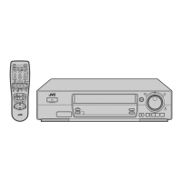
Visual breakdown of the unit's main assemblies and accessories.

PACKING AND ACCESSORY ASSEMBLY

List of packing materials and standard accessories included with the unit.

FINAL ASSEMBLY

Exploded view of the unit's final external assembly components.

MECHANISM ASSEMBLY

Detailed exploded view of the tape transport mechanism components.

Related product manuals