1-8 (No.MA124)
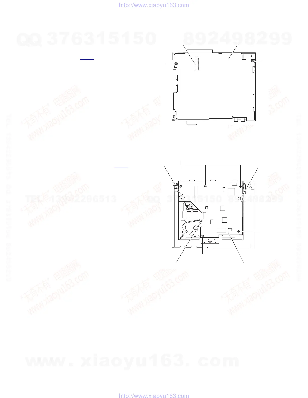
3.1.6 Removing the main board
(See Fig.7)
• Prior to performing the following procedure, remove the front
panel assembly, front chassis assembly, side panel, bottom
cover and rear bracket.
(1) Remove the two screws H attaching the main board.
(2) Disconnect the connector CN501
and take out the main
board.
Fig.7
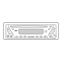
3.1.7 Removing the CD mecha control board
(See Fig.8)
• Prior to performing the following procedure, remove the front
panel assembly, front chassis assembly, side panel, bottom
cover, rear bracket and main board.
(1) Disconnect the card wire from the connector CN601
on the
CD mecha control board.
(2) Remove the five screws J attaching the CD mecha control
board.
(3) Release the claw f, and take out the CD mecha control
board.
Reference:
When attaching the CD mecha control board, attach it to the
claw f and pass the slot g of it into the boss of the CD mecha-
nism assembly.
Fig.8
Main board
H
H
CN501
CD mecha control board
CN601
J
J
J
Slot g
Claw f
w
w
w
.
x
i
a
o
y
u
1
6
3
.
c
o
m
Q
Q
3
7
6
3
1
5
1
5
0
9
9
2
8
9
4
2
9
8
T
E
L
1
3
9
4
2
2
9
6
5
1
3
9
9
2
8
9
4
2
9
8
0
5
1
5
1
3
6
7
3
Q
Q
TEL 13942296513 QQ 376315150 892498299
TEL 13942296513 QQ 376315150 892498299
http://www.xiaoyu163.com
http://www.xiaoyu163.com
 Loading...