KD-S6250/KD-S580
1-10
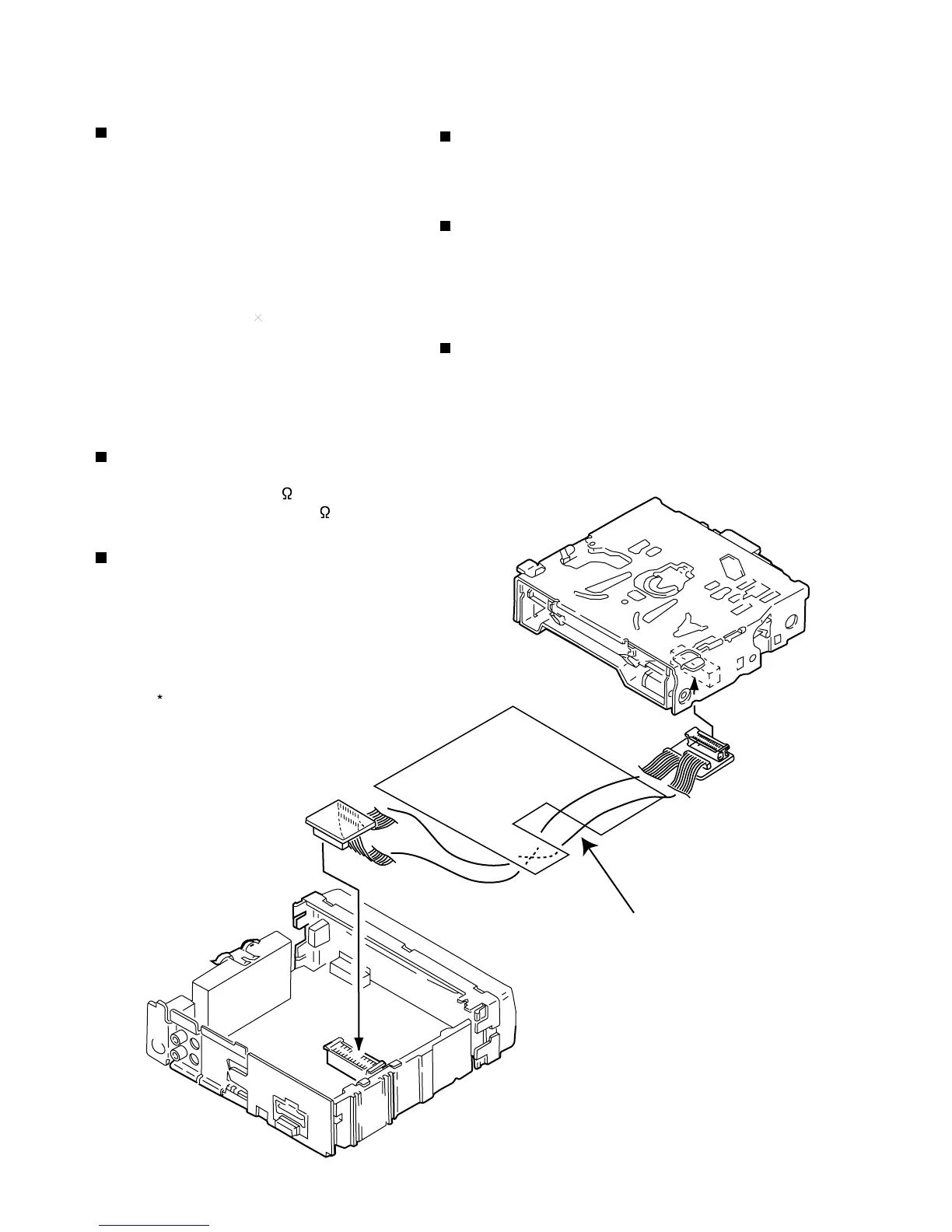
Prior to performing the following procedure, remove
the CD mechanism control board, the front bracket
(loading motor) and the CD mechanism ass’y.
Remove the two screws K and the feed motor ass’y.
1.
Removing the feed motor ass’y
(See Fig.10)
*Prior to performing the following procedure, remove
the CD mechanism control board, the front bracket
(loading motor), the CD mechanism ass’y and the
feed motor ass’y.
Detach the FD gear part of the pickup unit upward.
Then remove the pickup unit while pulling out the
part n of the FD screw.
1.
Remove the screw L attaching the nut push spring
plate and the pickup mount nut from the pickup unit.
Pull out the FD screw.
2.
Removing the pickup unit
(See Fig.10 and 11)
When reattaching the pickuap unit,
reattach the part o of the pickup unit,
then the part n of the FD screw.
ATTENTION:
Prior to performing the following procedure, remove
the CD mechanism control board, the front bracket
(loading motor), the CD mechanism ass’y and the
feed motor ass’y.
Turn up the CD mechanism ass’y and remove the
two springs p on both sides of the clamper arms.
Open the clamper arm upward.
Turn the turn table, and remove the two screws M
and the spindle motor.
1.
2.
Removing the spindle motor
(See Fig.12 and 13)
Fig.10
Fig.11
Fig.12
Fig.13
Spindle motor
p
p
Pickup unit
Part n
FD screw
Feed motor ass’y
FD gear
Pickup unit
Part O
K
Nut push spring plate
Pickup mount nut
Pickup unit
FD screw
L
M
M
 Loading...