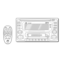
(No.MA081)1-29
3.3.4 Removing the side bracket assembly
(See Fig.8 to 10)
(1) Remove the screw A attaching the side bracket assembly.
(2) Detach the front side of the side bracket assembly upward
and pull out forward to release the joint i and j in the rear.
CAUTION:
When reassembling, make sure that the boss k of the
main chassis is set in the notch of the load rack under the
side bracket assembly. Do not reattach the load rack on
the boss k.
CAUTION:
After reattaching the side bracket assembly, confirm op-
eration.
Fig.8
Fig.9
Fig.10
A
Side bracket assembly
Side bracket assembly
Joint i
Joint j
Joint i
Joint j
Side bracket assembly
Boss k
Load rack
Boss k
Load rack
 Loading...