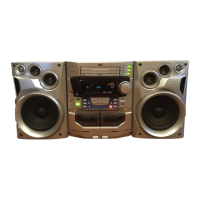
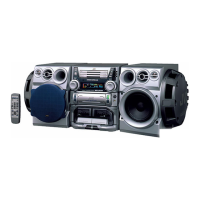
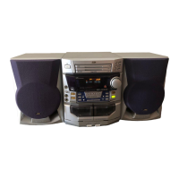
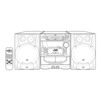
MX-J570V/MX-J680V
1-18
Prior to performing the following procedure, remove
the metal cover, CD changer mechanism assembly,
the front panel assembly, the microphone terminal
board assembly, the rolling panel assembly and the
main board.
Remove the relay board / fixing board (Refer to
Fig.20).
Remove the two screws K attaching the motor
bracket and remove the motor lead staple n.
Remove the two screws L attaching the shaft
bracket.
Remove the motor belt.
Remove the three screws M attaching the side
bracket.
Remove the shaft assembly from the rolling panel
assembly by lift up the shaft assembly upward.
Remove the drive motor upward.
1.
2.
3.
4.
5.
6.
7.
Removing the drive motor assembly
(See Fig.38 to 40)
Fig.20
Fig.38
Fig.39
Fig.39
Rolling panel assembly
W
X
Groove g
CN900
CN901
Relay board
Groove h
Fixing board
W
Relay board
X
Fixing board
L
K
Shaft bracket
Motor belt
Motor lead staple n
Shaft assembly
Drive motor
Motor bracket
M
Side bracket
Fig.40
 Loading...