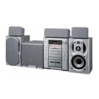
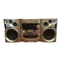
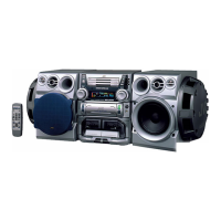
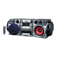
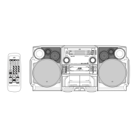
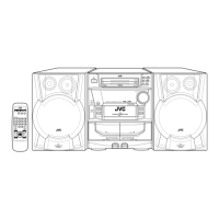
MX-J570V/MX-J680V
1-33
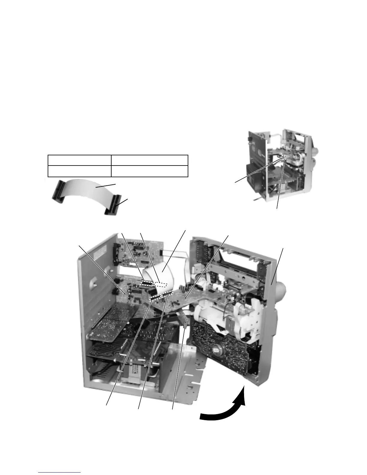
FLAT WIRE
FLAT WIRE
QUQ412-4020CJ
JIG-MXJ500
CONNECTOR Board x 2
CONNECTOR Board x 2
Diagnosis which uses extension wire method
System control P.C.board
1.Remove the metal cover and CD changer mechanism.
2.Remove the front panel assembly.
3.One screw A is removed, and relay board is removed.
4.As shown in fig.1, place the front panel assembly after
opening it outward using the right side of the front panel as
an axis.
5.The extension wire is connected with CN870 & CN871 on
the INPUT/OUTPUT board and CN860 & CN861 on the
main board.
Extension wire parts No.
Extension wire
Input/output board
Main board
Relay board
Relay board
CN870
A
CN860
CN871
CN861
Fig.1
Front panel assembly
 Loading...