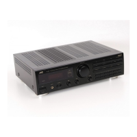
RX-7520VBK
1-8
Prior to performin
the followin
procedure, remove
the top cover and the front panel assembl
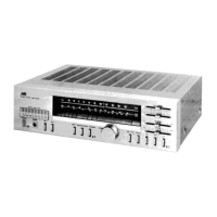
P
ll o
t th
vol
m
kno
on th
front
i
of th
front
panel and remove the nut attachin
the system
ontrol
o
r
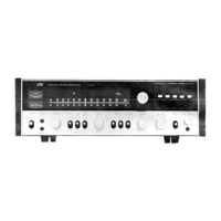
Remove the two screws Q attachin
the power
wit
h
o
r
Disconnect the harness from connector
N714 on
the power switch board
Remove the six screws R attachin
the system
control board on the back of the front panel
On the back of the front panel, release the six
oints
by pushin
the joint tabs inward.
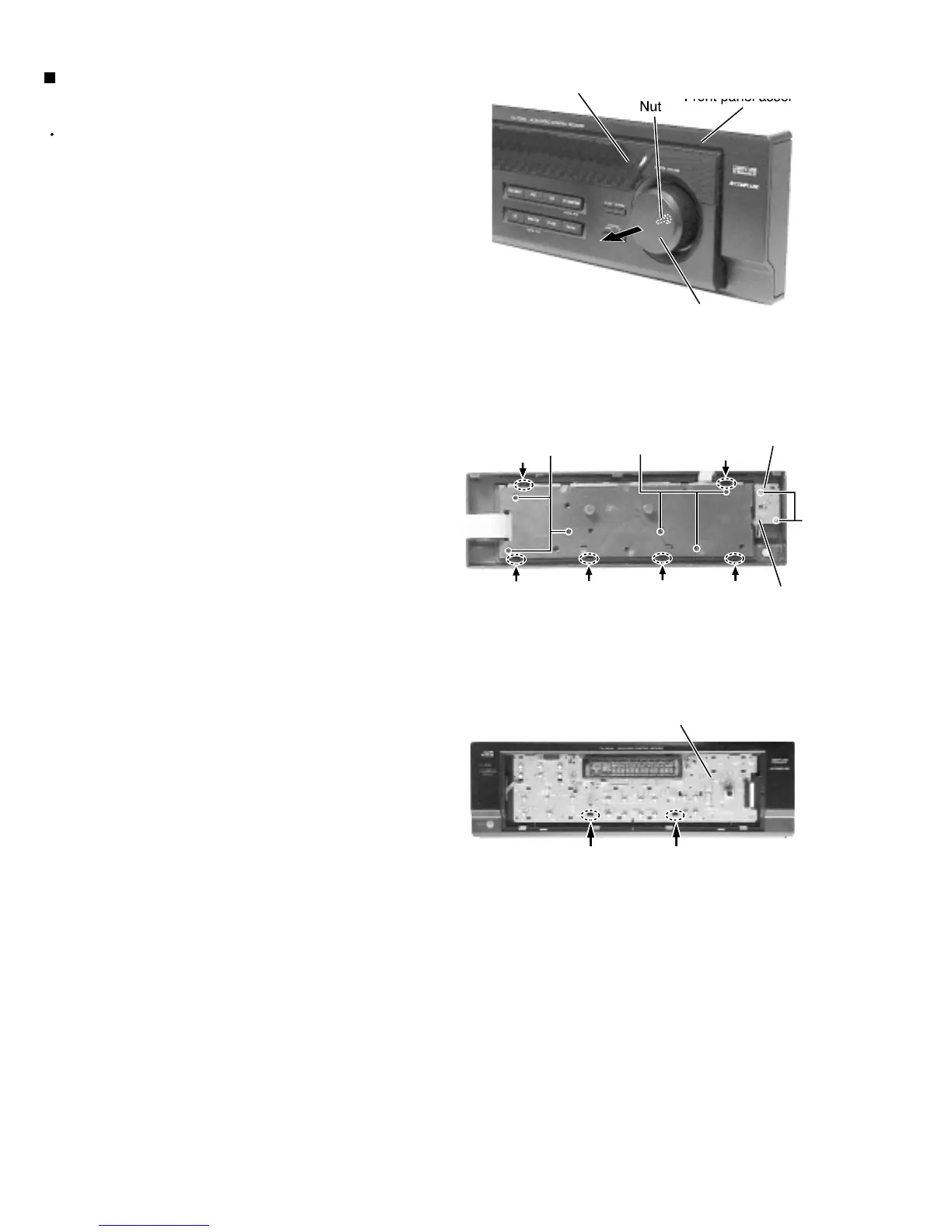
Remove the operation switch panel toward the front
Release the two hook attachin
the system control
o
r
Removin
the system control board
power switch board (See Fi
.18 to 20
Fi
.1
Fig.19
i
.2
Vol
m
kno
S
stem control boar
Pow
r
wit
o
r
N71
oin
oin
oin
oin
oin
oin
H
H
Operation switch pane
 Loading...