RX-8022PSL
1-4
Prior to performing the following procedure, remove
the top cover and rear panel.
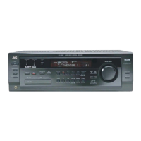
Cut off the tie bands.
Disconnect the harness from the connector CN393
on the compu link board (see fig.2).
Disconnect the harness from the connector CN721,
CN723 on the main board and CN722 on the Cch
amp. board.
Remove the two fasteners fixing the small board to
the audio input board and video board.
Draw out the DVD board upwards, disconnecting the
connector CN501, CN243, CN205, CN381 and
CN361 on the DVD board.
1.
2.
3.
4.
5.
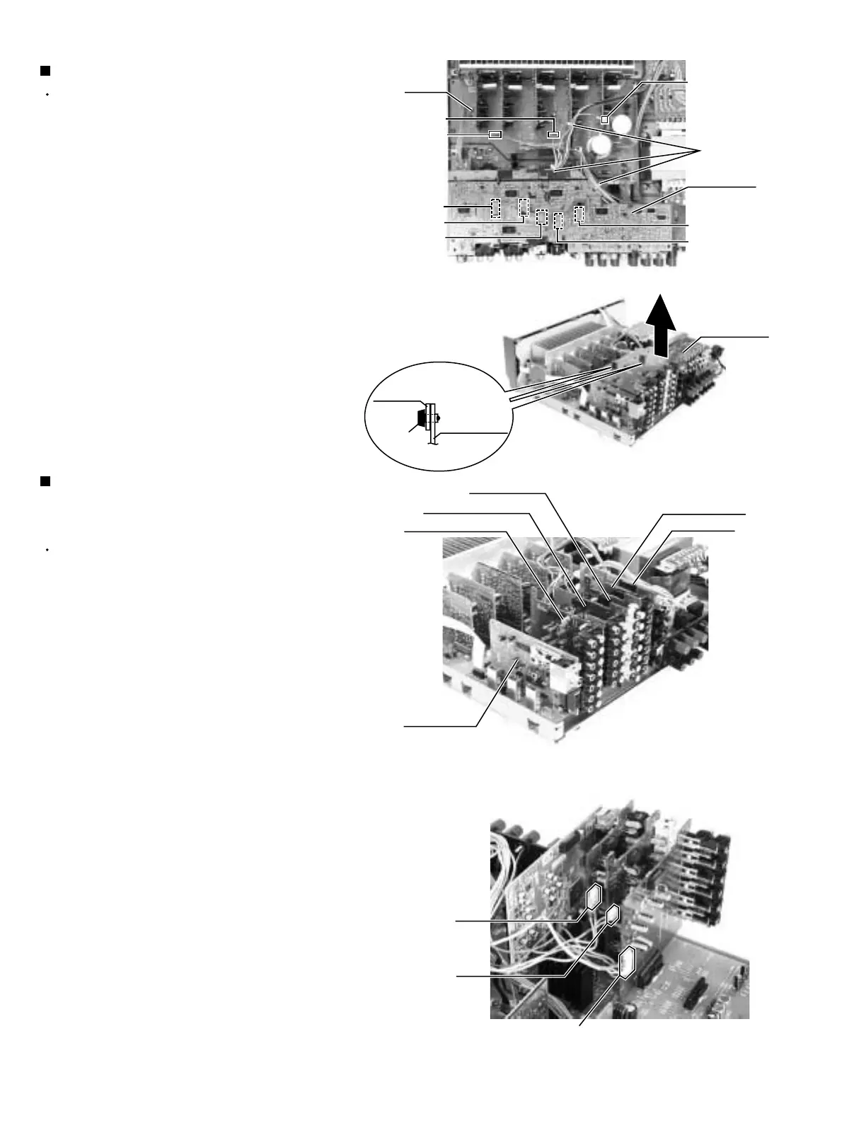
Removing the DVD board (See Fig.5 and 6)
Prior to performing the following procedure, remove
the top cover, rear panel and DVD board.
Remove the tuner board from the connector CN101
on the audio board.
Remove the audio input board from the connector
CN301 on the audio board.
Disconnect the harness from the connector CN416
and remove the video audio board from the
connector CN303 on the audio board.
Disconnect the harness from the connector CN206
and remove the video board from the connector
CN201 on the audio board.
Disconnect the harness from the connector CN244
and remove the S video board from the connector
CN241 on the audio board.
Remove the DSP board from the connector CN601
on the audio board.
1.
2.
3.
4.
6.
7.
Removing the each board of the tuner, the
audio input, the video audio, the video, the
S video and the DSP (See Fig.7 to 10)
Fig.5
Fig.6
Fig.8
Tie band
CN723
Tuner board
CN721
CN722
(on the Cch
amp. board)
DVD board
Main
board
CN361
CN381
CN243
CN501
CN205
Fig.7
Audio input board
Audio input board
&
Video board
Fastener
Small board
Video board
S Video board
Video audio board
DSP board
DVD board
CN244
(on the S
video board)
CN206
(on the
video board)
CN416
(on the video audio board)
 Loading...