LASER DEFUSER EX & EX2
(FRONT CUSTOM MOUNT WITHOUT FRAME)
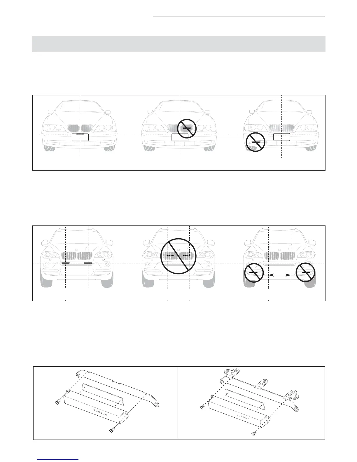
DIAGRAM B1
Diagram B3
BRACKET
TAPE
1/4” SCREW
LASER DEFUSER
BRACKET
TAPE
LASER DEFUSER
1/4” SCREW
WITHOUT
HORIZONTAL
TABS
WITH
HORIZONTAL
TABS
3. If utilizing the supplied universal mounting bracket(s), determine which holes will be used to mount the
Defuser module(s) to the vehicle. Remove the unused mounting tabs on the bracket(s) as needed.
4. Apply the supplied double stick tape directly to the Defuser module(s) and attach the module(s) to the
universal mounting bracket(s) with the included 1/4” screws ( diagram B3).
1/4”
SCREW
1/4”
SCREW
CENTERED & UN-
OBSTRUCTED
DO NOT PUT BEHIND GRILL
DO NOT OBSTRUCT VIEW
DO NOT MOUNT OFF CENTER
2. For the dual Defuser EX2, choose separate mounting locations on either side of the license plate area and/or
center of the vehicle. For proper performance, the EX2 modules should be spaced 18" apart from one
another, and cannot be obstructed in any way or recessed into the vehicle (see diagram B2).
DO NOT PUT BEHIND GRILL
DO NOT OBSTRUCT VIEW
DIAGRAM B2
1. For the single Defuser EX, choose a mounting location near the center of the vehicle that has a clear, unob-
structed view of the road . Units which are mounted off center, are recessed into the vehicle, or which are
obstructed in any way will not perform properly (see diagram B1).
If using an EX system, first separate the module from the license plate frame by removing the
two screws on the backside of the frame.
NOTE:
CORRECTLY SPACED
& UNOBSTRUCTED
DO NOT SPACE MODULES
MORE THAN 18” APART
 Loading...