G
Gabriel SandersJul 25, 2025
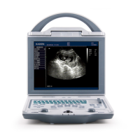
What to do if intermittent stripe, snow, or far-field interference appears on the Kaixin KX5600 screen?
- SStephanie GarciaJul 25, 2025
If you observe intermittent stripes, snow, or far-field interference on the screen, consider the following: * Examine the power supply for any spark interference. * Check the surrounding environment for potential interference sources like electric motors, ultrasonic atomizers, automobiles, computers, or other devices. * Ensure that the power plug/socket of the instrument and probe connectors are properly connected.