32
The boost voltage may be adjusted as follows:
1. Wire an AC RMS ammeter in series with one motor phase.
2. Run the motor unloaded at approximately 4 Hz (or 120 RPM).
3. Increase the boost until the ammeter reaches the motor nameplate rated current (Amps AC).
4. Using the Main Speed Potentiometer, slowly adjust the mo-
tor speed over a 1 – 15 Hz (0 – 450 RPM) range. If the motor
current exceeds the nameplate rating, decrease the boost
setting.
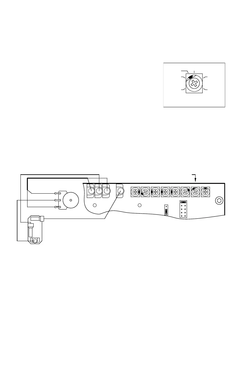
13.9 Jog (JOG) – The Jog feature requires the installation of a
Run-Stop-Jog Switch. The switch must be wired according
to Figure 44. The JOG Trimpot range is shown in Figure 43.
The orange Main Speed Potentiometer wire (wiper) which
connects to Terminal “P2” on the drive must be removed and
installed on Terminal “RUN” on the switch. The “JOG” Terminal on
the drive connects to “JOG” on the switch. Terminal “P2” on the drive connects to the center (com-
mon) terminal on the switch.
When the switch is in the “JOG” position, the JOG Trimpot
is used to set the “jog” speed. When the switch is in the “RUN”
position, the Main Speed Potentiometer is used for speed setting.
The Run-Stop-Jog Switch is available as an optional accessory. See Table 2 on page 9.
Run-Stop-Jog Switch
P3 P2
Orange (Wiper)
(JOG)
(P2)
White (Low) (P1)
Potentiometer
Violet (High) (P3)
Main Speed
CL JOG COMPBOOSTACCEL DECEL
JOG
MAX MIN
P1
J2
(SPDT - Center O)
(Wiper)
E
D
A
C
B
MA
J3
Figure 44 – Run-Stop-Jog Switch Connection (SPDT – Center O)*
35
JOG
(Shown Factory Set to 35% Frequency Setting)
0
25
100
75
50
Figure 43 – Jog
Trimpot Range
*Layout may vary.
 Loading...