Q.1.3 November 2017
Page 7
KE2 EvaporatorEfciency
Quick Start Guide
© Copyright 2017 KE2 Therm Solutions, Inc., Washington, Missouri 63090
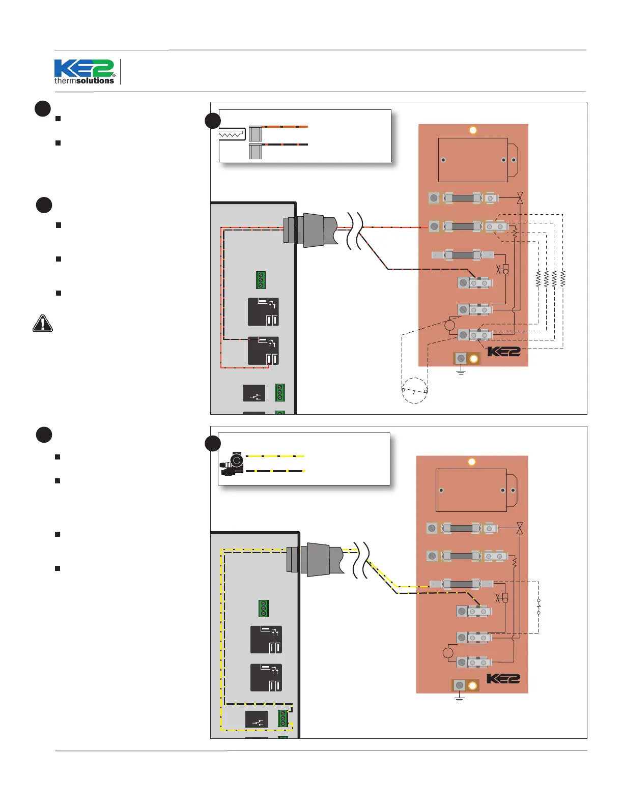
Evaporator wiring – Heater
Strip the ends of the wires being used for
heater control.
The heater wires can be attached to the
terminal block using either screw down
terminals or spade connectors.
18
Evaporator wiring – Liquid Line Solenoid
/Compressor
Strip the ends selected to control the liq-
uid line solenoid.
Attach the wire connected to the NO
terminal on the LL Solenoid/Compressor
relay on the controller, to the fused LL
SOLENOID/COMP terminal on the board,
as shown.
Attach the wire from the COM on the LL
Solenoid/Compressor relay on the control-
ler, to the L1/Line Voltage on the board.
Connect remaining LL Solenoid/
Compressor lead to L2/NEUTRAL terminal
on the board.
20
Remove defrost termination (Klixon®)
from circuitry
Attach the wire connected to the Heater
Relay COM terminal on the controller to
the L1 terminal on the board.
Attach the wire connected to the NO
terminal on the Heater Relay to the fused
HEATERS terminal on the board as shown.
Connect L2/NEUTRAL to the remain-
ing HEATERS terminal as shown using the
HEATER LIMIT SWITCH (or jumper).
The defrost safety should not be removed
from the circuit. Its purpose is to prevent
the heaters from over heating and causing
damage.
19
BL/BK
OR/BK
Y/BK
FAN/S
HEATERS
LL SOLENOID/COMP RELAY
BK/OR
L1
WT/R
L2
HS
GND
P/N 20996
12 AMP
20 AMP
3 AMP
OR NEUTRAL
HEATERS
thermsolutions
®
NO NC
COM
NO NC
COM
COM
NC
NO
COM
NC
N0
Solenoid Relay
Defrost
Relay
Fan
Relay
208-240
Power Input
Voltage Jumper
208-240 Default
L1
Ground
L2
COM
NC
NO
COM
NC
N0
Auxiliary Relay
HEATER LIMIT SWITCH
DEFROST HEATERS
R/W
BL/BK
BK
BL/BK
FROM
CONTROLLER
EC MOTOR
RELAY
BL/BK
OR/BK
Y/BK
FAN/S
HEATERS
LL SOLENOID/COMP RELAY
BK/OR
L1
WT/R
L2
HS
GND
P/N 20996
12 AMP
20 AMP
3 AMP
OR NEUTRAL
HEATERS
thermsolutions
®
NO NC
COM
NO NC
COM
COM
NC
NO
COM
NC
N0
Solenoid Relay
Defrost
Relay
Fan
Relay
208-240
Power Input
Voltage Jumper
208-240 Default
L1
Ground
L2
COM
NC
NO
COM
NC
N0
Auxiliary Relay
LIQUID LINE SOLENOID
N.C.
R/W
BL/BK
BK
BL/BK
FROM
CONTROLLER
EC MOTOR
RELAY
Orange with black stripe
12 AWG ag connectors
Black with orange stripe (L1)
12 AWG ag connectors
18
Yellow with black stripe
16 AWG stripped and retained
Black with yellow stripe (L1)
16 AWG stripped and retained
LLS/Compressor
20
 Loading...