List of p
Degrees 0.1 to 99.9 0.1
r1 Degrees -200 to r2 -200
r2 Higher value for SP Degrees r1 to 600 600
r4 Set Point variation Degrees 0.1 to 200 3
d0 Cooling or heating control Option Co/Ht Co
c0 Minimum stopping time Seconds 0 to 999 0
c2 Output status with probe error Option On/OFF On
P1 Ambient probe adjustment Degrees -99.9 to 99.9 0
P4 Decimal point Option no/yes yes
P5 3 wires Pt100 Option no/yes yes
E0 Digital input configuration Option OFF/Al/ES/HC OFF
H5 Access code to parameters Numeric 0 to 255 0
A0 Alarm 1 hysteresis Degrees 0.1 to 99.9 1.0
A1 Alarm 1 threshold Degrees 0.0 to 999 0
A2 Alarm 1 exclusion time Seconds 0 to 999 0
A3 Alarm 1 type Option OFF/HI/LO OFF
A4 Alarm 2 hysteresis Degrees 0.1 to 99.9 1.0
A5 Alarm 2 threshold Degrees 0.0 to 999 0
A6 Alarm 2 exclusion time Seconds 0 to 999 0
A7 Alarm 2 type OFF/HI/LO OFF
A8 Alarm verification time Seconds 0 to 999 0
r1 =
r2 = Higher value for SP
r4 = Set point variation for If digital input
configuration E0 ES this value modify the set point as follows
If d0
If d0
Cooling or heating control
c0 = Minimum stopping time of the load
c2 = Output status with probe error
P1 = Ambient probe adjustment
P4 = Decimal point
P5 = 3 wires Pt100.
E0 = Digital input configuration
H5 = Access code to parameters (it is set to 00 from factory)
A0, A1, A2, A3 = Alarm 1 parameters
arameters
Description Units Range Factory
SP Set Point Degrees r1 to r2 0
r0
Parameter descriptions
Differential or hysteresis
Lower value for SP
(energy saving)
SP = Set point. Temperature we wish to regulate the machine
(variable from r1 to r2)
r0 = Differential or hysteresis
Lower value for SP
energy saving.
= :
= Ht new SP = SP - r4
= Co new SP = SP + r4
d0 =
If d0 = Ht and TS is the temperature of ambient probe:
If TS >= SP the load is disconnected
If TS <= SP - r0 the load is connected
If d0 = Co then:
If TS <= SP the load is disconnected
If TS >= SP + r0 the load is connected
no = 2 wires, yes = 3 wires
OFF = Digital input disabled
Al = External alarm (if input is short-circuited)
ES = Energy Saving. Set Point value is modified in r4.
HC = if input is short-circuited, it changes to Heat or Cold
depending of d0 value.
if d0 = Heat it changes to Cold mode.
if d0 = Cold it changes to Heat mode.
If A3=OFF alarm 1 disabled
If A3=HI then a high-temperature alarm is set:
if TS >= SP+A1 the alarm 1 is activated
if TS <= SP+A1-A0 the alarm 1 is de-activated
If A3=LO then a low-temperature alarm is set:
if TS <= SP-A1 the alarm 1 is activated
if TS >= SP-A1+A0 the alarm 1 is de-activated
The alarm 1 is not activated until the time since instrument is turn
on is higher than A2
Option
A4, A5, A6, A7 = Alarm 2 parameters (similar to alarm 1)
A8 = Alarm verification time. Time since the alarm situation
occurs until its signalling.
Parameter programming
Led indication, buzzer and display messages
Alarm validation
(It affects to Alarm 1, Alarm 2 and
External alarm)
Set Point (SP) is the only parameter the user can
access without code protection.
•Press SET. SP text will appear on the display.
•Press SET again. The real value is shown on the display.
•The value can be modified with the UP and DOWN arrows.
•Press SET to enter any new values.
•Press SET and DOWN at the same time to quit
programming or wait one minute and the display will
automatically exit programming mode.
Access to all code protected parameters.
•Press SET for 8 seconds. The access code value 00 is shown on
the display (unit comes with code set at 00 from factory).
• With the UP and DOWN arrows, code can be set to user needs.
•Press SET to enter the code. If the code is correct, the first
parameter label is shown on the display (SP).
• Move to the desired parameter with the UP and DOWN
Keys.
•Press SET to view the value on the display.
• The value can be modified with the UP and DOWN arrows.
•Press SET to enter the value and exit.
• Repeat until all necessary parameters are modified.
•Press SET and DOWN at the same time to quit programming or
wait one minute and the display will automatically exit programming
mode.
*The keyboard code can be reset to ZERO by turning off the
controller and turning it on again while keeping the SET key
depressed.
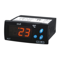
The led OUT indicates if the load is connected or not.
In normal operation, the probe temperature will be shown on the
display.
In case of alarm or error, the following messages can be shown (the
alarm led is ON and buzzer sounds):
• Err = Memory Error.
• ooo = Open Probe Error.
• --- = Short-circuit Probe Error.
• A1H = High temperature alarm 1.
• A1L = Low temperature alarm 1.
• A2H= High temperature alarm 2.
• A2L = Low temperature alarm 2.
•ALE = External alarm.
In case of alarm the internal buzzer and alarm led is activated. The
display shown the corresponding message. The buzzer and display
message can be silenced pressing the SET and DOWN arrows at
the same time. If alarm continues after A8 it is signalling again.
ETDT1765I_110829
Electrónica Keld, S.L. Phone: +34 976 429 099
Pol.Ind. Empresarium. C/Lentisco, 15 Fax:+34 976 593 532
50720 - La Cartuja Baja, ZARAGOZA E-mail: keld@keld.es
Spain Web: http://www.keld.es
 Loading...