The LX-24 is a 24 VAC or 24 VDC Passive Infrared (PIR) occupancy
sensor. The LX-24 provides isolated relay contacts that are normally
open or normally closed. This PIR-type sensor can integrate with HVAC
or EMS systems.
The LX-24 passive sensing system reacts to changes in infrared
energy (moving body heat) within the coverage area. Sensor placement is
important with PIR sensors; the sensor must directly “see” motion
of an occupant in order for detection to occur.
The effective coverage distances may be slightly less than the maximum
sensing distance, depending upon obstacles such as furniture or
partitions, and this must be considered when planning the number
of sensors and their positioning.
The LX-24 sensor can be mounted at various heights. Mounting heights of
less than 8 feet decrease the range and increase the sensitivity to smaller
motions. Conversely, mounting heights greater than 8 feet increase the
range and decrease the sensitivity to smaller motions. At heights greater
than 12-14 feet, you risk reduced sensitivity.
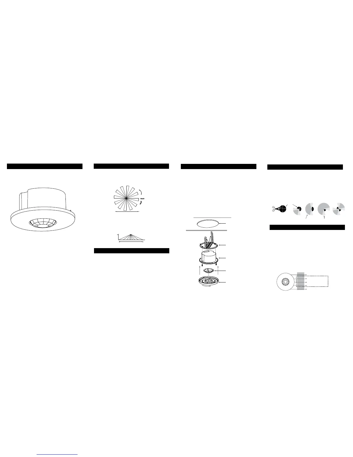
1. If using the ceiling attachment ring, bend the securing straps up so
the sensor housing can be inserted, and attach it to the sensor with
the provided screws
2. Attach the mask, if using, into the lens recess and onto the securing
pins of the cover.
3. Attach the cover to the rear housing; align tabs on inside of cover
to notches on outside perimeter of rear housing, place cover on
sensor, and twist clockwise to lock.
4. Insert the assembled sensor into the ceiling hole, and if using
the mask turn the sensor so that the unmasked part of the lens is
toward and centered on the area to be covered.
5. Bend the ceiling attachment ring straps behind the hole to secure.
CAUTION:
TURN POWER OFF AT CIRCUIT BREAKER BEFORE WIRING SENSOR.
• Connect 24 VAC or +24 VDC supply to the Red and return to the Black
wire from the sensor.
Isolated relay (Rated for 1A@24 VDC or 24 VAC)
Connect the wires necessary to the application that requires this output.
• Green (normally closed) open when occupancy is detected
• Orange (common) must be used for proper operation
• Yellow (normally open) closed when occupancy is detected.
Cover (with lens)
Mask (optional)
(Cut for desired coverage)
Rear housing
Ceiling attachment ring
(bend behind ceiling to secure)
3" Hole
Ceiling
Top View
Mask
Cut mask into sections
for desired coverage,
shown right.
Coverage area Reduced sensitivity
It has a fresnel lens eld of view of 360°. Coverage shown in the
diagram below is maximum and represents coverage for half-step,
walking motion, with no barriers or obstacles.
COVERAGE PATTERNS
DESCRIPTION
PLACEMENT
WIRING DIRECTIONS
MASKING
INSTALLATION
An insert mask is supplied to allow elimination of coverage in unwanted
spaces. The mask is cut as needed and mounted onto anchor pins in the
sensor’s cover.
Important: For full coverage, no mask is needed.
Important: The assembled sensor must be turned so the unmasked
portion of the lens faces the coverage area prior to securing sensor to
mounting location.
Note: There is a small area of reduced sensitivity
corresponding to the lighter areas in the examples below.
Red
24 VAC or +24 VDC
24 VAC or 24 VDC return
Normally closed contact Isolated
Relay
Output
Normally open contact
Common
Green
Orange
Yellow
Black
 Loading...