Do you have a question about the KeLi XK3101 and is the answer not in the manual?
Details key technical specifications of the weighing transducer, including precision, resolution, and update rate.
Lists technical details such as excitation voltage, signal range, and relay contact capacity.
Details the recommended working and saving temperature and humidity ranges for the transducer.
Provides the physical dimensions of the weighing transducer in millimeters.
Explains panel installation and cabinet requirements for securely mounting the weighing transducer.
Guides on connecting the weighing transducer, including power supply and load cell signal inputs.
Details how to connect the weighing transducer to the AV 220V power supply, including fuse information.
Explains RS232 and RS485 serial port connections, including wire definitions and socket types.
Explains the two-point relay output connection and touching points, noting relay capacity.
Explains the data frame structure, baud rates, and data transmission for RS232 and RS485 interfaces.
Details parameters like maximum weighing value and divisional reading for accurate calibration.
Provides a step-by-step guide for calibrating the weighing transducer, often requiring professional supervision.
Guides on selecting calibration points (two-point or three-point) based on indicator display.
Describes the process for calibrating the zero point of the weighing transducer.
Details calibrating the weighing value using a standard poise, ensuring it's over 20% of max capacity.
Explains how to input the loaded poise value and adjust glittering bits during calibration.
Covers calibration for non-linearity, especially when linearity is not good, using a second point of load.
Describes an intermediate step in calibration where the indicator displays a sequence of dashes.
Details inputting the maximum poise value and adjusting glittering bits for calibration.
Explains how to accept and save the calibrated results or choose temporary validity.
Guides on choosing between 0-20mA, 4-20mA, 0-5V, or 0-10V analog output modes.
Explains how to set the weight range for analog output, from zero to max or a custom section.
Details setting the bottom value (AL) for analog output when using a custom weight range.
Details setting the top value (AH) for analog output, ensuring it's higher than the bottom value.
Explains how to reset the analog output bottom and top values to their original settings.
Details the button sequence required to enter the parameter selection menu.
Explains various F2 parameters like ADC speed, tare, zero clearing, auto zero-set, and dynamic testing.
Specifies options for setting the ADC transmitting speed rate (7.5Hz to 60Hz).
Details the parameter for enabling or prohibiting the tare function and its range.
Explains parameters for clearing to zero, including prohibition or allowance with different ranges.
Covers settings for automatic zero tracking, specifying tracking speeds.
Details parameters for enabling or disabling dynamic testing and its sensitivity levels.
Explains how filter intensity affects stability and response time, with numbers indicating strength.
Defines the auto zero-set range that is applied when the indicator is turned on.
Explains the logic for relay actions based on weight thresholds in separate selective mode.
Details the logic for relay actions based on fixed value thresholds in fixed value mode.
Guides on setting up the relay output, including comparative values and mode selection.
Recommends setting relay output to zero if the function is not used.
Details the button sequences for configuring baud rate, mode, address, and data transmission.
Guides on selecting between command mode and continuous transmit mode for the serial interface.
Explains how to set or amend the indicator's address for multi-indicator communication.
Details options for transmitting weight data or the number of divisions.
Describes the self-test sequence upon power-on, including analog output mode display and initial readings.
Lists and explains various error codes (E1-E5) related to overload, calibration, or hardware protection.
Provides guidelines for regular maintenance, cleaning, and environmental considerations for the indicator.
Details the frequency and methods for routine cleaning and maintenance of the indicator.
Offers solutions for common malfunctions like no display, E1 errors, or persistent self-test indicators.
Provides steps to diagnose and resolve issues related to the absence of an analog output signal.
Guides on checking baud rate and transmit mode to resolve issues with serial interface data transmission.
Offers solutions for relay output failures by checking comparative values and working modes.
The Keli XK3101 (KM05) Weighing Transducer is a versatile industrial control device that combines weight display and analog signal output. Manufactured by Keli Electric Manufacturing (Ningbo) Co., Ltd., it is designed for various industrial control applications requiring precise weight measurement and signal conversion.
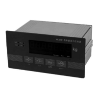
The KM05 acts as a weighing transducer, converting weight data into analog signals. It features a high-precision 24-bit A/D converter for signal acquisition and a 16-bit D/A converter for analog output. The device includes a 7-segment LED digital display (0.56 inch character height) and a 20-segment light pole display for visual feedback. It offers two-point (off) relay output, configurable for weight-selective or fixed-value modes. Isolated digital communication interfaces (RS232 or RS485) are available, and analog output modes can be set to 4-20mA, 0-20mA, 0-5V, or 0-10V.
Loading Capacity:
Performance:
Power Supply:
Environmental Conditions:
Main Specification:
Installation: The KM05 adopts panel installation and is housed in a small aluminum box. The hatch dimensions for cabinet installation are 150+0.5mm x 75+0.5mm. Mandrels on both sides must be removed before insertion into the cabinet and then re-fixed to ensure a secure installation.
Connections:
Display Panel: Features four buttons:
Indicator Lights:
Calibration:
Analog Output Modes:
Parameter Selection (F2 Menu):
Relay Output Modes:
Serial Interface Setup (F3 Menu):
Power-on Self-Test: Displays numbers 0-9, then analog output mode (e.g., "0-20" for 0-20mA), and pre-set baud rate if in continuous transmit mode. Finally, it displays "--------" to catch zero.
Prompt Examinations: Pressing the [Fn] button in normal working mode cycles through parameters like relay comparative values (1PXXXXX, 2PXXXXX) and analog output bottom/top weight values (ALXXXXX, AHXXXXX).
| Brand | KeLi |
|---|---|
| Model | XK3101 |
| Category | Transducer |
| Language | English |