EasyManua.ls Logo

Kenwood KRC-5001 User Manual

Kenwood KRC-5001
47 pages
To Next Page IconTo Next Page
Page #1 background imageLoading...
Page #1 background image
HIGH-POWER
CASSETTE
REGEIEn
RC-5001
©
=RVICE
MANUAL
1987-1
PRINTED
IN
JAPAN
BS1-3199-00(1)
952.
Knob
{Button}
Pane!
ass‘y
Knob
(Button)
Knob
{Button}
(K27-1581-14)
(A20-5094-02)
{K27-1767-08}
(K27-1580-14)
Knob
(Button)
Front
board
Knob
(Button)
Knob
{Button}
(K27-1766-08}
;
(AS2-0102-03)
|
{K27-1768-05)
|
(K27-1579-14}
Panel
ass’y
{X90-2440-10)
:
;
Knob
(Button)
Knob
Knob
(Burttan}
Knob
(Button)
(K27-177
1-08)
Knob
(K29-1889-04)
(K27-1772-08)
{K27-1776-08)
Knob
(Button)
¢
X27-1770-08
(K29-1889-04)
Knob
(Button)
ae
2008!
Knob
(K27-1773-08)
heed
sana
Knob
(Button!
Knob
(K29-1888-04}
Knob
(Button)
(K29-1768-08})
{K29-
1888.04)
(K27-1775-08}
Knob
{Button}
{K27-1781-08}
Top
cover
(A52-0100-7
2}
Cord
with
plug
(E30-1529-05}
Cord
with
DIN
cannestor
{E3G-1527-05)
x
2
*
Refer
to
Parts
List
on
page
35.
Question and Answer IconNeed help?

Do you have a question about the Kenwood KRC-5001 and is the answer not in the manual?

Kenwood KRC-5001 Specifications

General IconGeneral
TypeCar Receiver
BrandKenwood
ModelKRC-5001
Tuner BandsAM/FM
DIN Size1 DIN

Summary

Disassembly for Repair

Unit Disassembly Procedures

Detailed steps for dismantling the receiver unit.

Block & Level Diagram

System Signal Flow Overview

Illustrates internal signal paths and functional blocks of the receiver.

Circuit Description

Component Overviews by Unit

Lists components for Tuner, Control, and Synthesizer units.

µPD1708G Microprocessor Details

Pin configuration, terminals, and key matrix operations.

Key Matrix and Switch Functions

Explains key matrix layout, connections, and initialization.

Operational Key Functions

Details functions of SEEK, DX/LOC, ME, BAND, and LOUDNESS keys.

RCAL and NR Key Operations

Explains the operation of RCAL and NR select keys.

Adjustment

Alignment Procedures

Detailed steps for aligning FM, AM, and Cassette sections.

Test Equipment Setup

Diagram showing the setup of test equipment for adjustments.

Exploded Views

Mechanism Assembly Diagram

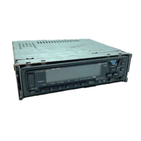
Exploded view illustrating the internal mechanism components.

Main Unit Assembly Diagram

Exploded view showing the main unit components.

Parts List

Component Listings

Comprehensive list of all parts with their numbers and descriptions.

Packing

Package Contents and Accessories

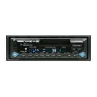
Lists items included in the product packaging and their part numbers.

Specifications

Technical Performance Data

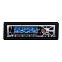
Detailed electrical and performance specifications of the KRC-5001 receiver.

Related product manuals