35
EN
35
EN
5.3 - Bar release
If it is necessary to manually adjust the barrier bar, proceed as follows
(Fig. 17):
- Disconnect the power supply.
- Insert the supplied release key and remove the pad lock, insert the
Allen key and rotate it by 90°.
- In this way it is possible to release the internal reducer system to
allow for emergency manoeuvring.
5.4 - Bar angle adjustment
In the event that the bar limit stops must be adjusted, proceed as
follows (Fig. 18):
- Loosen the locknut located on the upper crosspiece of the box
- Adjust the screw to the desired height
- Perform the manual manoeuvre.
- To re-activate the transmission, simply turn the Allen key to return it
to its initial position and then close the lock.
- Now you can restore the power supply and check that everything is
in good working order.
- Re-tighten the locking nut again
- Repeat the operation with the other stop
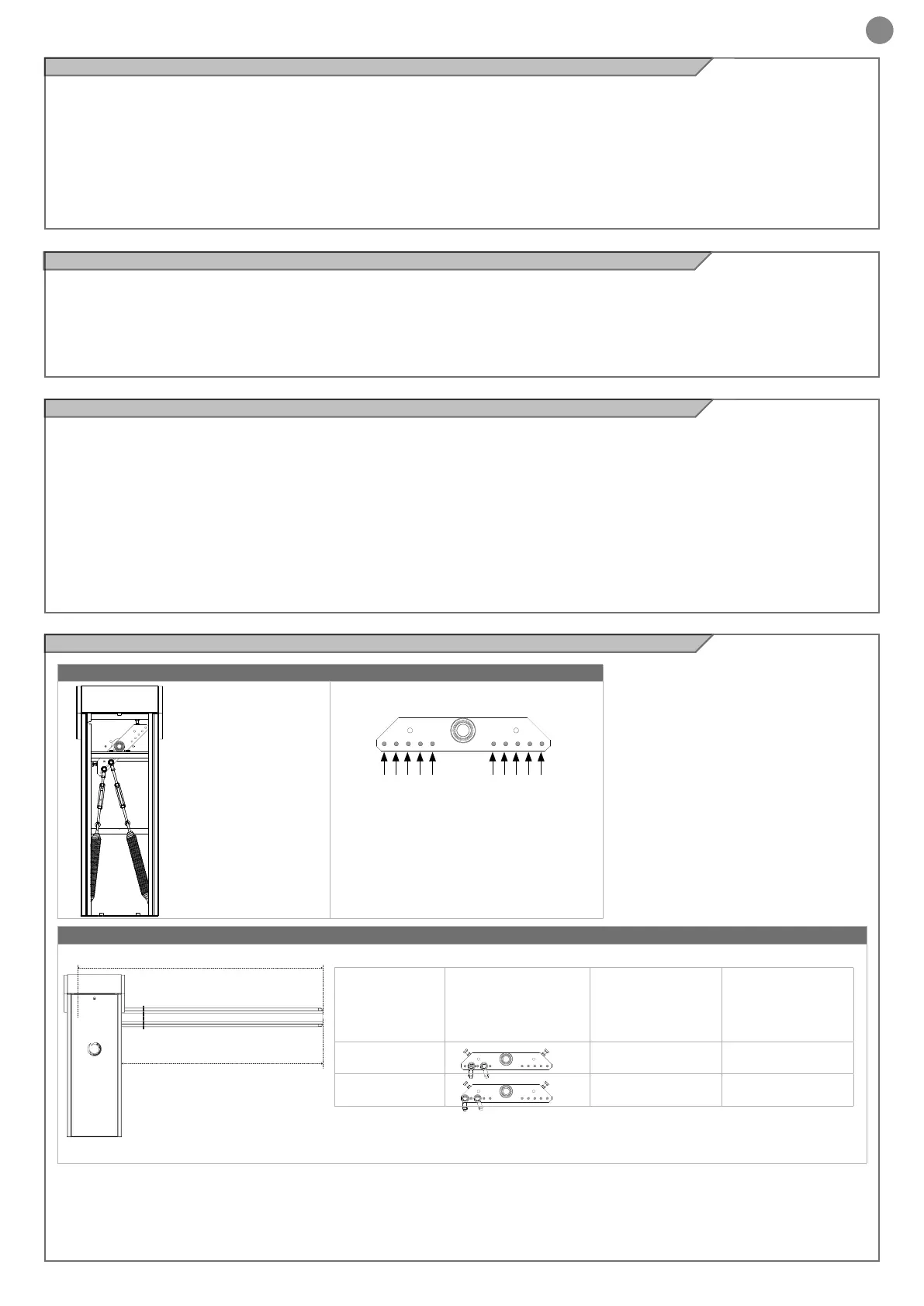
5.6 - ALT324KF Accessories and bar weight balancing
5.5 - Barrier conguration with accessories
Before carrying out, during installation, the rst balancing of the bar,
the barrier must be congured according to the accessories actually
installed.
The following diagrams (Par. 5.6 for ALT324KF, Par. 5.7 for ALT424K,
Par. 5.8 for ALT624K) show the optimal xing positions of the articu-
lated joint heads of the tensioners with respect to the balance lever
for your barrier conguration, i.e. by model (ALT324KF, ALT424K or
ALT624K), by length of the bar and according to the chosen acces-
sories.
It is therefore necessary to compare these positions with the "factory"
ones and if they do not match, loosen the screws that x the articula-
ted heads of the tensioners to the balance lever and reposition them
accordingly:
- starting from the "factory" conguration, install the bar in a vertical
position. Make sure the bar is locked in this position
- identify, on the basis of the following diagrams, the most suitable po-
sition of the articulated joint heads of the tensioners and x them with
the screws to the corresponding holes in the balance lever, tightening
the tensioners by a few turns so as to partially increase the springs'
tension
KEY
ONLY BAR
L= LUNGHEZZA ASTA
PL=LARGHEZZA PASSAGGIO (L-300 mm)
example of spring positioning:
2 + 4 = HOLE NUMBER
L=BAR LENGTH
PL=PASSAGE WIDTH (L-300 mm)
HOLE NUMBERS
3+5
1+3
1 52 43 34 25 1
L = BAR LENGTH
(mm)
POSITION
SUGGESTED VALUE
FOR LS1 PARAMETER
SUGGESTED VALUE
FOR LS2 PARAMETER
2400 52 55
3000 55 68
 Loading...